Sensor Parameters
This section describes the configuration parameters based on sensor types.
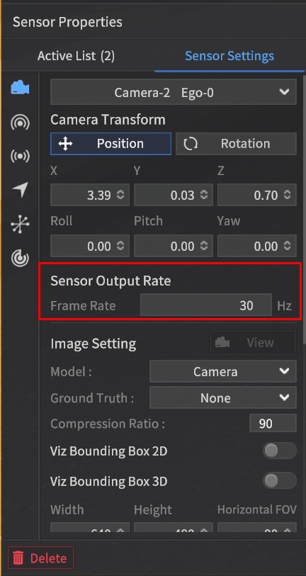
Camera
Configure the camera's X, Y, Z (based on the vehicle axes), Roll, Pitch, Yaw, resolution, FOV, and ground truth output.
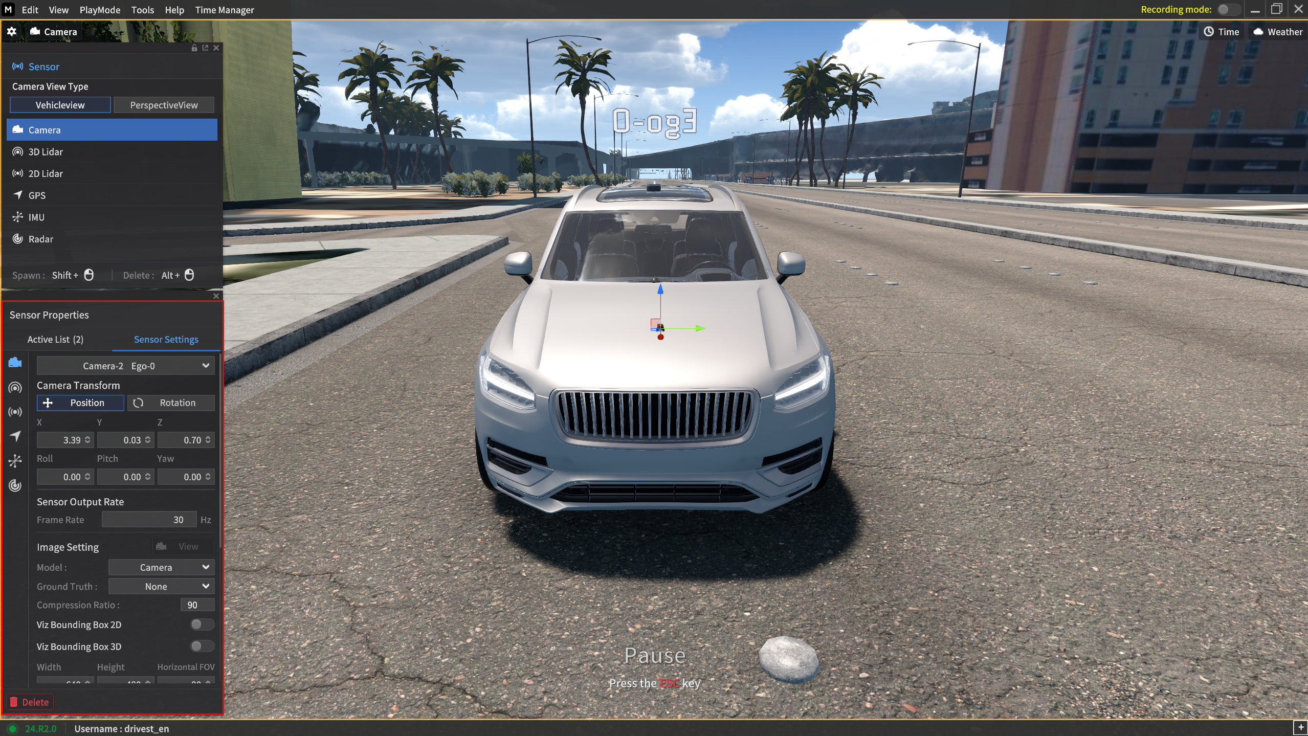
Frame Rate (Hz)
Specify the data transmission frequency for the camera sensor.
 Depending on the target FPS value and simulator FPS, the transmission may occur at a rate lower than the configured frame rate.
The frequency can be set between 5 and 60 Hz in 1 Hz increments.
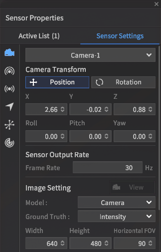
Model
Select the supported camera sensor model in the Model field.
Camera : The default model
Fish Eye Camera: Same parameter as the camera model, but this is a camera model which a fisheye lens applied.
Lab Camera: Same feature and parameter as the camera model, but this is a camera model which has a different physical appearance. ADD-ON SERVICE
Physical Camera : This model supports actual camera formats. ADD-ON SERVICE
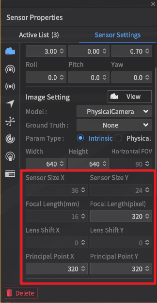
For the Physical Camera, it is possible to configure the Radial Distortion Parameters (k1, k2, k3).
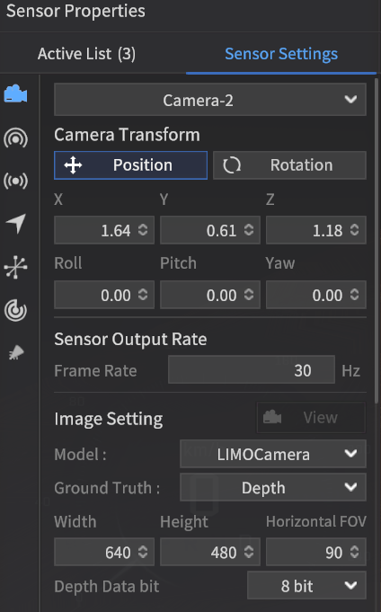
LIMO Camera: This camera model supports None (Intensity) and Depth types as Ground Truth data. ADD-ON SERVICE
The View screen of objects detected by the Camera sensor for each model is shown below.
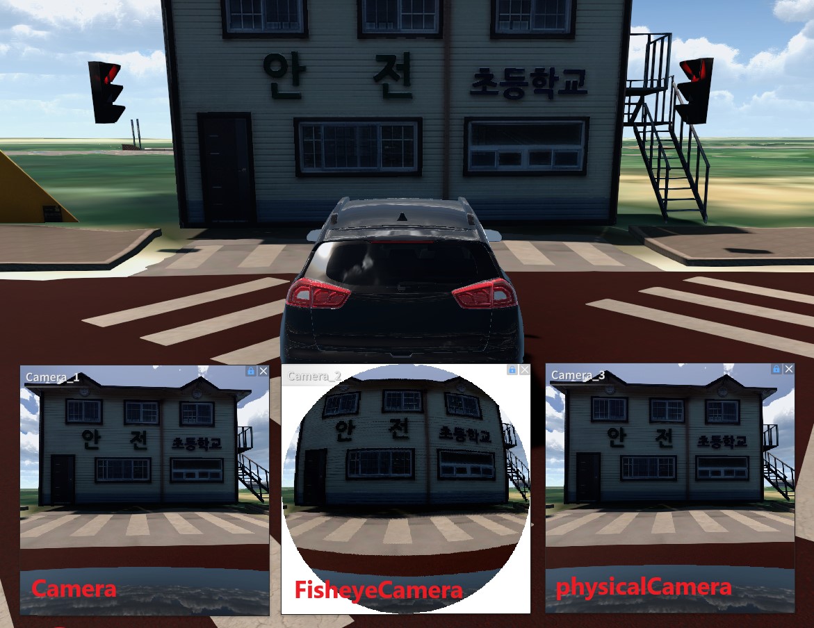
Camera View
Ground Truth
Ground Truth refers to the reference data detected by the camera sensor within the simulator.
In the camera sensor model, the following formats are supported as types of Ground Truth data:
Additional parameters are added only when the Depth type is selected.
Intensity : RGB image
Semantic : Semantic image
Instance : Instance image
Depth : Depth image
In the Fish Eye Camera model, Depth type is not supported.
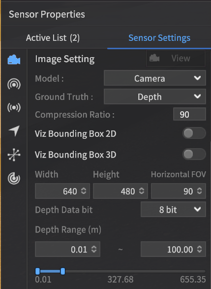
When selecting the Depth type, the following parameters must be configured:
Depth Data bit
Number of bits to represent Depth Data: Determines the bit depth used to represent the depth information.
Variable that defines the actual depth resolution: This variable directly affects the depth precision.
Selectable values: 8-bit, 16-bit.
Depth Range (m)
Min Depth
Minimum distance for Depth Ground Truth output
Objects that are closer than the minimum distance will be represented in black (0)
Max Depth
Maximum distance for Depth Ground Truth output
Objects that are further than the maximum distance will be represented in black (0)
You can select a custom range for Depth Ground Truth output within the range [0.01, 655.35].
You can generate ground truth (GT) data images for each GT type by using the sensor capture feature.
None | Semantic | Instance | Depth |
|---|---|---|---|
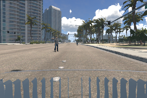 | 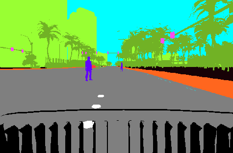 | 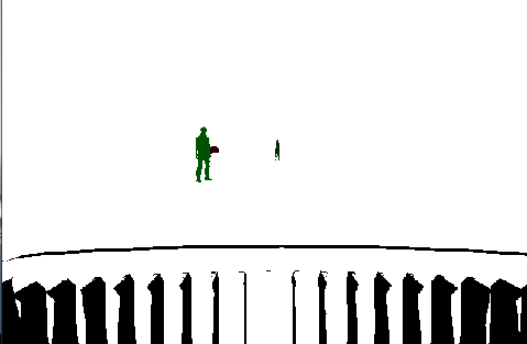 | 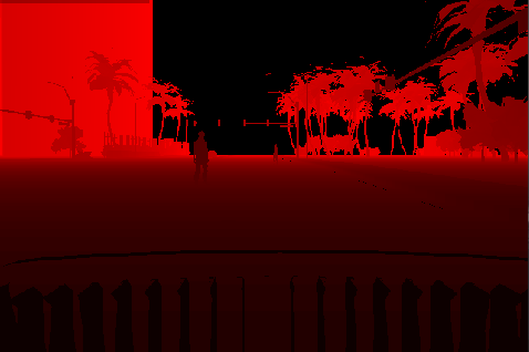 |
For the Depth type, the memory usage may increase depending on the image size and output frequency (Hz) generated by the simulator.
2D LiDAR
Configure the 2D LiDAR settings for X, Y, Z (based on the vehicle axes), Roll, Pitch, Yaw, Model, and Intensity Type.
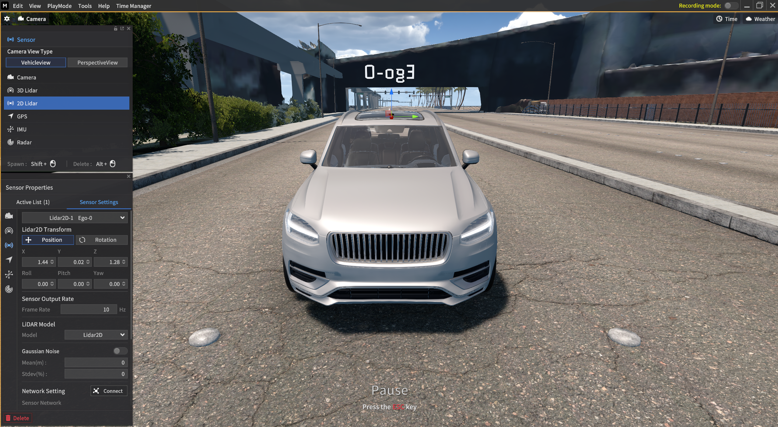
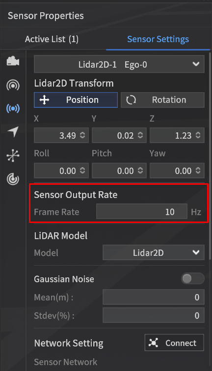
Rotation Rate(Hz)
Specify the data transmission frequency for the 2D LiDAR sensor.
- When entering the
roslaunchcommand under ROS Network, it is necessary to modify the RPM option.
(Refer to the LiDAR ROS Network Settings : Communication Protocols for Sensors | 2D-LiDAR ) - Depending on the Target FPS value and the simulator FPS, the set rotation rate can be transmitted lower than the set value.
- The range values that can be set varies by LiDAR model.
For more information about the Sensor Noise, go to Create Sensor Noise .
Gaussian Noise
Gaussian noise can be applied to the Distance values of the 2D LiDAR.
The application of this noise can be toggled On/Off.
Parameters
Mean: The mean value of the noise distribution (Unit: m, Range: -1 to 1 m, Type: Float)
Stdev: The standard deviation of the noise distribution relative to the distance (Unit: %, Range: 0 to 1%, Type: Float)
For more information about the Sensor Noise, go to Create Sensor Noise .
3D LiDAR
Configure the 3D LiDAR settings for X, Y, Z (based on the vehicle axes), Roll, Pitch, Yaw, Model, and Intensity Type.
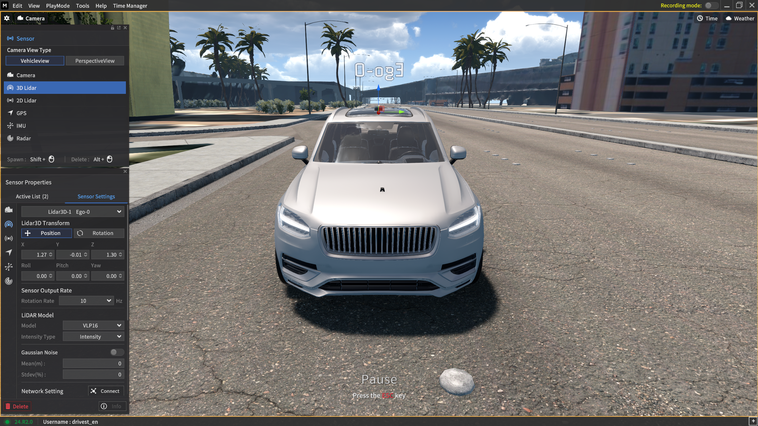
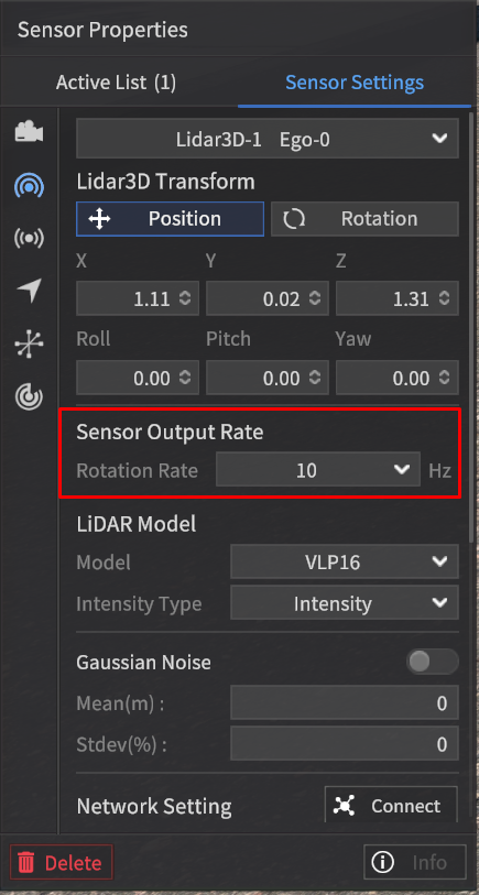
Rotation Rate(Hz)
Specify the data transmission frequency for the 3D LiDAR sensor.
- When entering the
roslaunchcommand under ROS Network, it is necessary to modify the RPM option.
(Refer to the LiDAR ROS Network Settings : Communication Protocols for Sensors | 3D-LiDAR ) - Depending on the Target FPS value and the simulator FPS, the set rotation rate can be transmitted lower than the set value.
- The range values that can be set varies by LiDAR model.
For more information about the Sensor Noise, go to Create Sensor Noise .
Gaussian Noise
Gaussian noise can be applied to the Distance values of the 3D LiDAR.
The application of this noise can be toggled On/Off.
Parameters
Mean: The mean value of the noise distribution (Unit: m, Range: -1 to 1 m, Type: Float)
Stdev: The standard deviation of the noise distribution relative to the distance (Unit: %, Range: 0 to 1%, Type: Float)
For more information about the Sensor Noise, go to Create Sensor Noise .
GPS
Set the X, Y, Z coordinates (based on the vehicle's axis), as well as the Roll, Pitch, and Yaw values for the GPS.
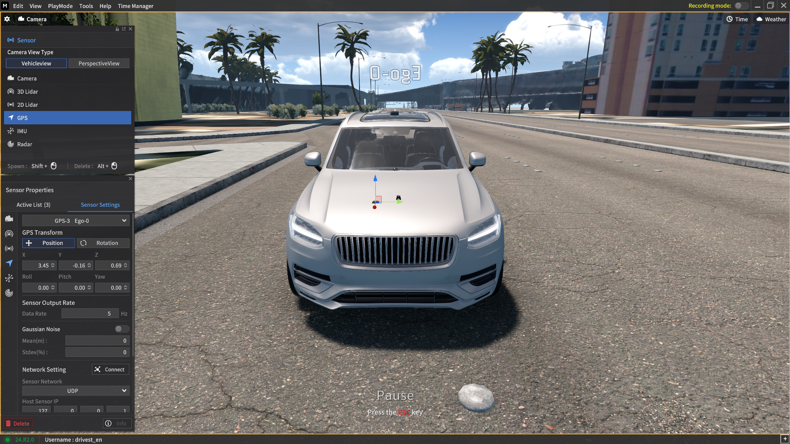
In the GPS sensor, parameter values that represent the characteristics of the sensor, such as the Camera's Width, Height, and GT type, cannot be modified.
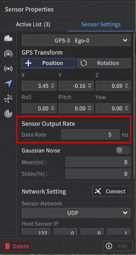
Data Rate(Hz)
Specify the data transmission frequency for the GPS sensor.
- Depending on the Target FPS value and the simulator FPS, the set rotation rate can be transmitted lower than the set value.
The Sensor Output Rate can be set between 1 and 30 Hz in 1 Hz increments. (For the default value, check out the below red-colored box.)
For more information about the Sensor Noise, go to Create Sensor Noise .
IMU
Set the X, Y, Z coordinates (based on the vehicle's axis), as well as the Roll, Pitch, and Yaw values for the IMU.

In the IMU sensor, parameter values that represent the characteristics of the sensor, such as the Camera's Width, Height, and GT type, cannot be modified.
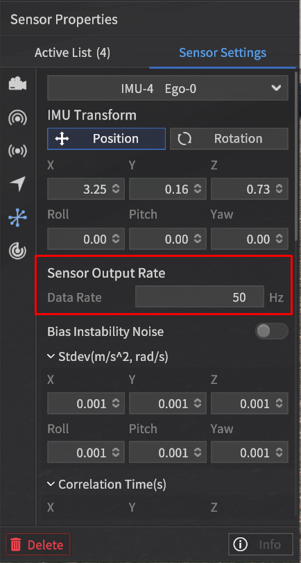
Data Rate(Hz)
Specify the data transmission frequency for the IMU sensor.
- Depending on the Target FPS value and the simulator FPS, the set rotation rate can be transmitted lower than the set value.
The Sensor Output Rate can be set between 5 and 50 Hz in 1 Hz increments.
For more information about the Sensor Noise, go to Create Sensor Noise .
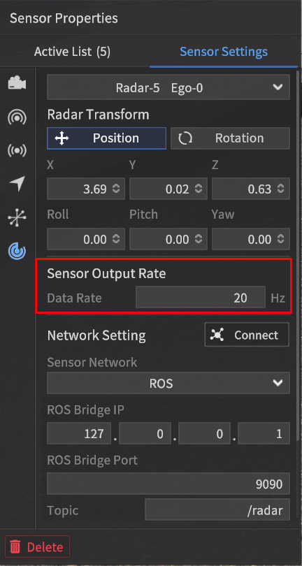
Radar
Set the X, Y, Z coordinates (based on the vehicle's axis), as well as the Roll, Pitch, and Yaw values for the Radar.
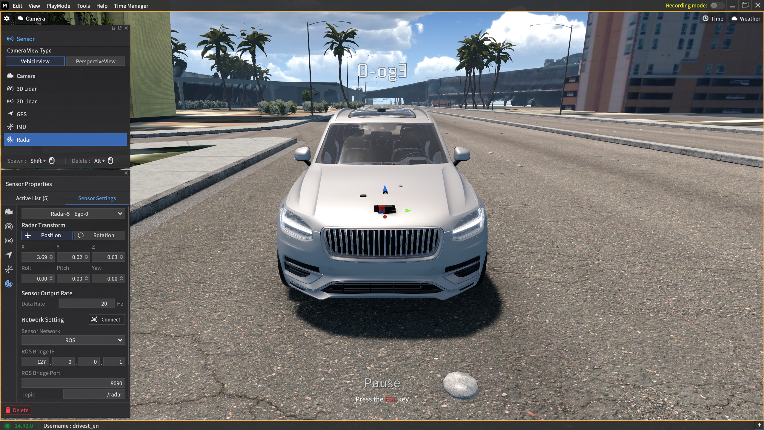
In the Radar sensor, parameter values that represent the characteristics of the sensor, such as the Camera's Width, Height, and GT type, cannot be modified.
Data Rate(Hz)
Specify the data transmission frequency for the Radar sensor.
- Depending on the Target FPS value and the simulator FPS, the set rotation rate can be transmitted lower than the set value.
The Sensor Output Rate can be set between 5 and 20 Hz in 1 Hz increments.
When the Viz Radar Range is activated, it displays Radar Point Clouds (yellow dots) for the objects detected by the Radar Sensor.