
Communication Protocols for Sensors
This section explains sensor communication protocols such as ROS and UDP for transmitting sensor detection data externally.
This explains the message protocols and data structures supported by each type of sensor communication.
Camera
The simulator supports ROS, UDP, and Apollo for camera sensor communication.
ROS
The protocol information for ROS messages transmitted by the camera sensor is as follows:
Default Topic Name : /image_jpeg/compressed
Message: sensor_msgs/CompressedImage (sensor_msgs/CompressedImage Documentation)
FrameID : Camera
Unlike other Ground Truth(GT) types, ROS message of camera depth image is as follows:
Default Topic Name : /image
Message: sensor_msgs/Image (http://docs.ros.org/en/noetic/api/sensor_msgs/html/msg/Image.html)
FrameID : Camera
UDP
The protocol information for UDP messages transmitted by the camera sensor is as follows:
Raw image data is transmitted using JPEG compression.
Even with the same resolution, the packet size and number of packets may vary each time.
If the JPEG packet size exceeds 64,987 bytes, it will be divided and transmitted in multiple packets of 64,987 bytes each.
Data Packet Structure
A general UDP packet structure for sending camera sensor data is as follows:
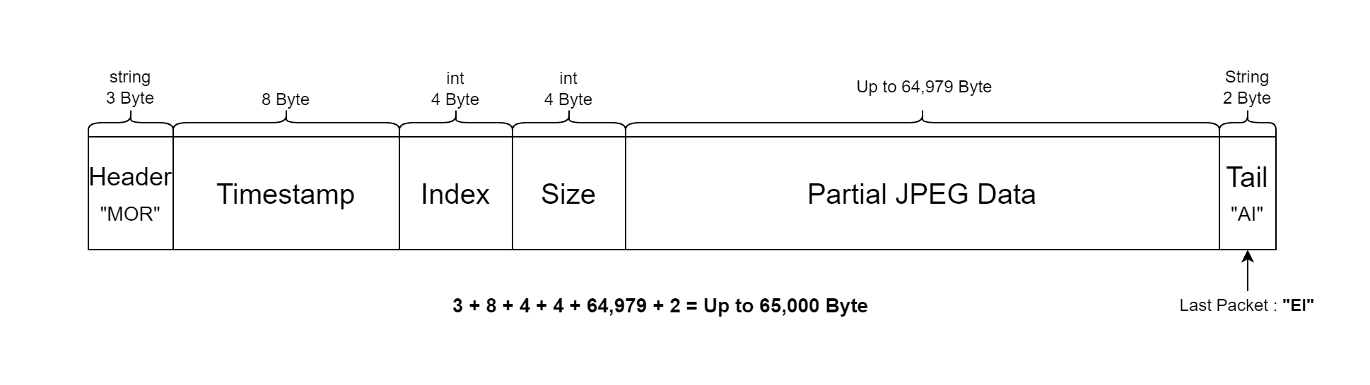
Header (3byte) : Packet Header value. “MOR.”
Timestamp (8byte) : TotalSecond(4byte) + Nanosecond(4byte).
Index (4byte) : Index of JPEG Data Block in the packet.
Size (4byte) : Size of JPEG Data Block in the packet.
Partial JPEG Data (Changeable, Max. 64,979bytes) : Compressed partial JPEG data.
Tail (2byte) : Tail value of the packet. “AI”. If it is the last packet, “EI”
2D/3D BBox Data Packet Structure
The 2D/3D bounding box data for Vehicle, Pedestrian, and Obstacle objects (excluding Traffic Lights) is transmitted together in a single UDP packet.
This data is sent only when the object is present in the camera view.
If the objectX data packet size exceeds 64,987 bytes, it will be transmitted in multiple packets of 64,987 bytes each.
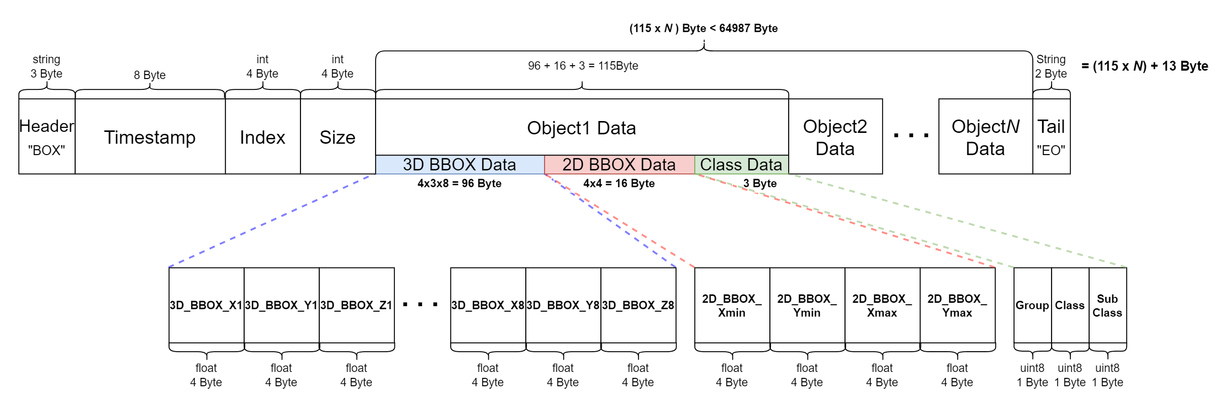
UDP Packet Field (총 (115 x N) + 13 byte)
Header (3byte) : Explains the packet data type.
Fixed value as “BOX”.
Timestamp (8byte) : TotalSecond(4byte) + Millisecond(4byte).
Index (4byte)
Size (4byte)
Object1 Data Block (96 + 16 + 3 = 115 byte) : Data Block for each object.
3D BBOX (4x3x8 = 96 byte) : Outputs the 8-point corner values of the 3D bounding box..
2D BBOX (4x4 = 16 byte) : Outputs the expression values of the 2D bounding box.
Class (3 byte) : Tag information of the object.
Tail (2byte) : Tail value of the packet, “EO.”
Object class values are represented by an RGB number triplet (e.g., [255, 255, 255]) and are based on the color scheme used in MORAI SIM for instance segmentation. The full table is attached below:
2D LiDAR
The simulator supports ROS and UDP for 2D LiDAR sensor communication.
ROS
The configuration method is same as the camera sensor, and it follows the below message protocol.
Message Type : sensor_msgs/LaserScan (https://docs.ros.org/en/melodic/api/sensor_msgs/html/msg/LaserScan.html)
Default Topic Name : /lidar2D
FrameID : Lidar2D-1
UDP
The protocol information for UDP messages transmitted by the 2D LiDAR sensor is as follows:
2D LiDAR sensor protocols vary by manufacturer.
The UDP packet structure for sending 2D LiDAR sensor data is as follows:
2D LiDAR Model
MORAI LiDAR
Data Packet Structure
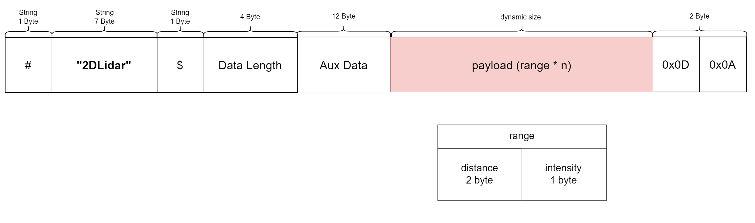
MORAI LiDAR
Total Size : 1107 byte
Payload Size : 1080 byte
Name | Value | Type | Field | Len [byte] | Description | Units | ||
|---|---|---|---|---|---|---|---|---|
| 1 | start_indicator | 0x23 | byte | 0 | 1 | “#” |
| |
| 2 | header_name | “2DLidar” | byte[7] | 1-7 | 7 |
|
| |
| 3 | doller_indicator | 0x24 | byte | 8 | 1 | “$” |
| |
| 4 | data_length | 1080 | uint32_t | 9-12 | 4 |
|
| |
| 5 |
aux_data | tx |
| float | 13-16 | 4 |
|
|
| 6 | ty |
| float | 17-20 | 4 |
|
| |
| 7 | heading |
| float | 21-24 | 4 |
|
| |
| 8 | Payload |
| byte[1080] | 25-1104 | 3 * 360 |
|
| |
| 9 | tail01 | 0x0D | byte | 1105 | 1 |
|
| |
| 10 | tail02 | 0x0A | byte | 1106 | 1 |
|
| |
3D LiDAR
The simulator supports ROS and UDP for 3D LiDAR sensor communication.
ROS
The configuration method is same as the camera sensor, and it follows the below message protocol.
Message Type : sensor_msgs/PointCloud2 (https://docs.ros.org/en/melodic/api/sensor_msgs/html/msg/PointCloud2.html)
Default Topic Name : /lidar3D
Same as the PointCloud2 definition in the Velodyne official driver.
There are 2 ways to receive 3D LiDAR ROS data.
Set up a sensor network in ROS after spawning the 3D LiDAR sensor in the simulator.
Set up a sensor network using UDP after spawning the 3D LiDAR sensor in the simulator, then convert the data to ROS using the Velodyne package.
Install Velodyne_pointcloud
$ sudo apt-get install ros-{$ROS_DISTRO}-velodyneRun roslaunch
if VLP16,
$roslaunch velodyne_pointcloud VLP16_points.launchif HDL32,
$roslaunch velodyne_pointcloud 32e_points.launchif HDL64,
$roslaunch velodyne_pointcloud 64e_S3.launchFollow the existing Velodyne official driver for the 3D LiDAR setup, but for HDL64, use the 64e_s3-xiesc.yaml file located in the etc folder of the link below.
Enter the RPM value into the point cloud of the running 3D LiDAR (Example: HDL32).
roslaunch velodyne_pointcloud 32e_points.launch rpm:={RPM Value}
• {RPM Value} : Input the corresponding value to the set rotation rate.
◦ RPM = Rotation Rate * 60e
◦ Example) When set to 5Hz → input 300.
◦ If not entering RPM value, the default value is 600 (10Hz).
When checking the RPM value in Veloview, the “No RPM” issue may occur depending on the version of Veloview.
: The updated Veloview 5.x version may not display the RPM value, while the Veloview 4.1.3 version has been confirmed to display it correctly.
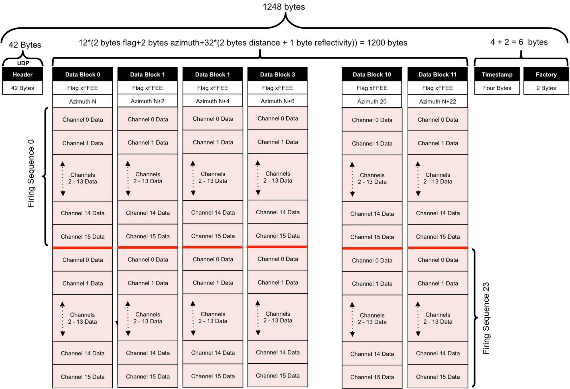
UDP
The 3D LiDAR protocol provided by the MORAI simulator follows the Velodyne protocol as below.
GPS
The configuration method is same as the camera sensor, and it follows the below message protocol.
ROS
Message Type : morai_msgs/GPSMessage
Default Topic : /gps
Type Description : GPS information
UDP
The configuration method is same as the camera sensor, and it follows the below message protocol.
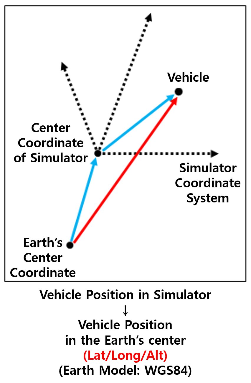
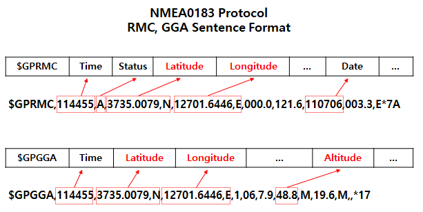
The sensor follows the NMEA0183 protocol and receives data in two formats simultaneously: RMC and GGA sentences.
Format Type (char): GPRMC/GPGGA. This indicates the format type.
Time (float): The timestamp when the GPS information is received.
Vehicle Position Information (Lat/Long/Alt, float): Latitude, longitude, and altitude measured by the GPS sensor.
IMU
ROS
The configuration method is same as the camera sensor, and it follows the below message protocol.
Message Type : sensor_msgs/Imu (sensor_msgs/Imu Documentation (ros.org))
Default Topic : /Imu
Type Description : IMU information
UDP
The configuration method is same as the camera sensor, and it follows the below message protocol.
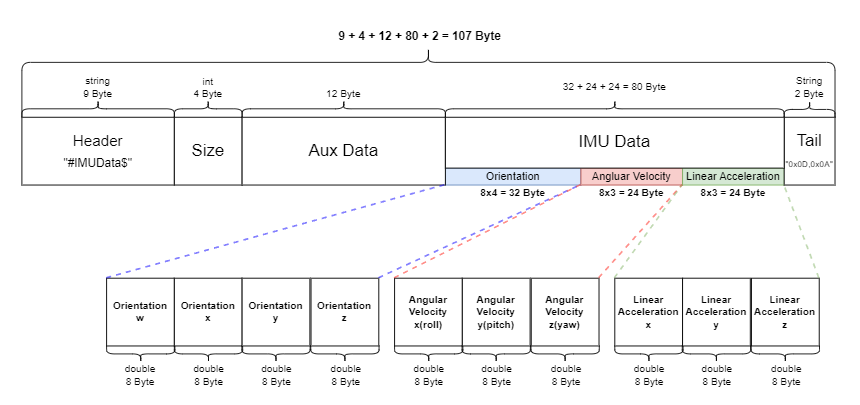
UDP Packet Field (107 bytes total)
Header (9 bytes) : Packet Header value. “#IMUData$“
Size (4 bytes) : Indicates the size of the IMU Data in the packet. Value: “80“
Aux Data(12 bytes) : Additional data field. Fixed value: “0”
IMU Data(32 + 24 + 24 = 80 bytes) : IMU Data Block
Orientation (8 x 4 = 32 bytes) : Quaternion representation of the IMU sensor’s orientation. Each quaternion component (x, y, z, w) is 8 bytes.
Angular Velocity (8 x 3 = 24 bytes) : Angular velocity values of the IMU sensor for each axis (X, Y, Z), in radians per second (rad/s). Each value is 8 bytes.
Linear Acceleration (8 x 3 = 24 bytes) : Linear acceleration values of the IMU sensor for each axis (X, Y, Z), in meters per second squared (m/s²). Each value is 8 bytes.
Tail (2 byte) : The packet's tail value: “0x0D, 0x0A“
Radar
ROS
Message Type : morai_msgs/RadarDetections.msg
Default Topic : /radar
Type Description : radar information
Header header
uint16 point_id
float32 x
float32 y
float32 z
float32 azimuth
float32 rangerate
float32 rcs
Radar(for RVIZ visualization)
Message Type : sensor_msgs/PointCloud
Default Topic : /radar
Type Description : radar pcd information