Sensor Detection Data
This section explains the data formats and structures detected by each sensor.
3D LiDAR
The detection data generated by the 3D LiDAR sensor mainly consists of two types of files:
a bin file containing point cloud data, and a text file containing ground truth data for 3D bounding boxes.
Point Cloud Data
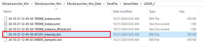
The Point Cloud data detected by the 3D LiDAR sensor is saved in the following format and can have Intensity, Semantic, or Instance types based on the sensor configuration:
File Format: bin file
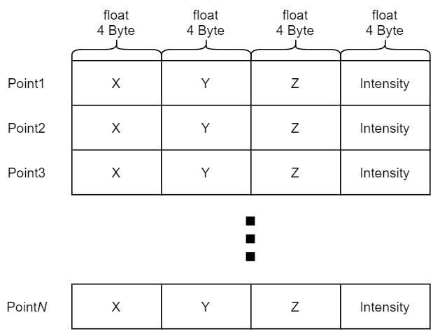
Data Structure: The
binfile contains 4-byte values for each point, with the x, y, z coordinates and intensity stored sequentially without spaces. The origin of the point cloud is the position where the LiDAR is mounted.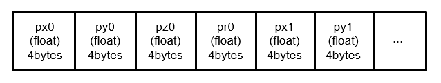
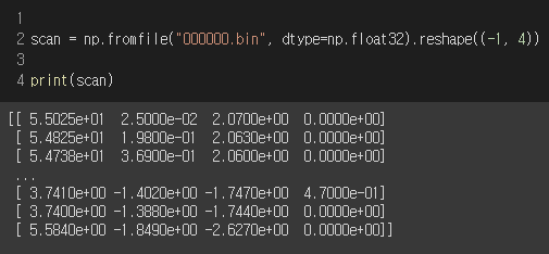
For Python users, you can load the 3D LiDAR point cloud data using the numpy library’s fromfile function as shown below:
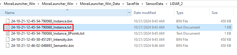
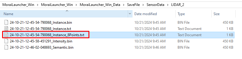
The storage location is SaveFile/SensorData/LIDAR_*, where the * corresponds to the filename, which is determined by the date and time the point cloud was saved.
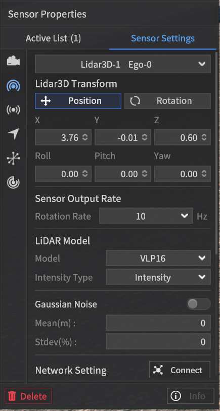
Intensity Type
This setting outputs the Intensity values of each point, just like an actual LiDAR sensor. To enable this, set the Intensity Type to "Intensity" in the Sensor Settings.
File format: bin file
Each line contains the X, Y, Z coordinates in a Orthogonal coordinate system and the corresponding intensity value for a single point (for N points, there will be N lines).
When intensity values are transmitted over communication protocols like UDP, they are represented within the range of 0 to 255.
However, when saved to a file, the intensity values are stored within the range of 0 to 1.
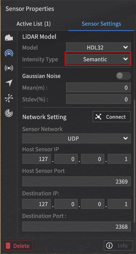
Semantic Type
In the Intensity Field, instead of outputting intensity values, this type outputs values corresponding to object classifications.
To enable this, set the Intensity Type to Semantic in the Sensor Settings.
The Semantic type data from the LiDAR sensor is mapped to intensity values based on the same labeling color map used for the Semantic type data in the camera sensor.
For detailed information, refer to the Labeling Color Map used in the Semantic Segmentation data of the camera sensor.
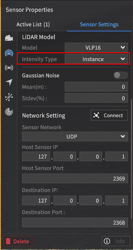
Instance Type
In the Intensity Field, instead of outputting intensity values, this type outputs classification values for objects such as vehicles, pedestrians, and obstacles.
To enable this, set the Intensity Type to Instance in the Sensor Settings.
The point cloud data of the Instance type contains intensity values according to the labeling color map for objects such as Vehicles, Pedestrians, and Obstacles.
Class | Intensity (unassigned integer 8) |
|---|---|
Vehicle | 0 ~ 149 |
Pedestrian | 150 ~ 254 |
Obstacle | Random values in 50-unit increments (e.g., 50, 100, 150, 200, 250, 45, 90, …) |
The values are assigned sequentially starting from 1 based on the order in which the objects appear, regardless of whether they are classified as Vehicle, Pedestrian, or Obstacle.
No assignment value is given for objects other than Vehicle, Pedestrian, or Obstacle.
Example:
Color: Tag | Intensity Field Value | |
Tag of each point | Intensity PointCloud | Instance PointCloud |
Vehicle | intensity1 | 1 |
Pedestrian | intensity2 | 2 |
Pedestrian | intensity3 | 3 |
Obstacle | intensity4 | 4 |
Building | intensity6 | 0 |
POINT_OUTSIDE_FOV *When a point goes beyond the detection range of the LiDAR sensor. | 0 | 0 |
… | … |
|
3D Bounding Box
When the Ground Truth (GT) setting of the LiDAR sensor is configured to Instance, the corresponding 3D Bounding Box ground truth data is generated as:
a text file in the format of { }_instance.txt
a text file in the format of { }_instance_8Points.txt
To enhance the perception performance of the Autonomous Vehicle (AV), all three rotation angles of the 3D Bounding Box object are provided.
The 3D Bounding Box file (.txt) includes Roll and Pitch in addition to Yaw.
An example structure of the ground truth data for the 3D Bounding Box detected by the LiDAR sensor for a single vehicle object is shown below.
1] { }_instance.txt
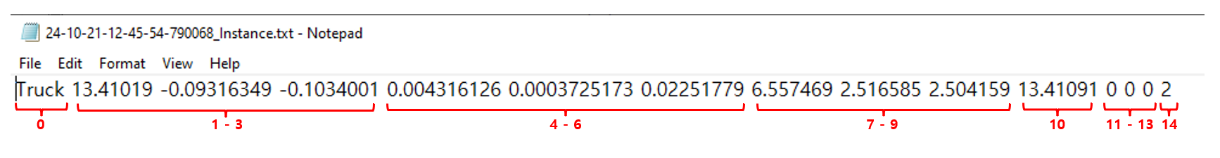
The information for each value that consists of the ground truth data of the 3D Bounding Box detected by the LiDAR sensor is as follows:
0: Class of the 3D Bounding Box, classified into three major categories (Vehicle, Pedestrian, Object).
1-3: Center coordinates (center_x, center_y, center_z) of the 3D Bounding Box (unit: m).
These coordinates represent the origin of the object coordinate system calculated based on the LiDAR coordinate system.
The LiDAR coordinate system follows the ISO 8855 convention, where the X-axis points forward, the Y-axis points to the left, and the Z-axis points upward.
4-6: Roll (rotation about the x-axis), Pitch (rotation about the y-axis), and Yaw (rotation about the z-axis) of the 3D Bounding Box (unit: radians).
These values represent the rotation angles of the object coordinate system calculated based on the LiDAR coordinate system.
7-9: Size of the detected object, represented as size_x (width in the x direction), size_y (width in the y direction), and size_z (height in the z direction) (unit: m).
10: Relative distance from the sensor to the object (unit: m).
11-13: Relative velocity of the object with respect to the sensor in the x, y, and z directions (unit: m/s).
14: Unique ID of the detected object.
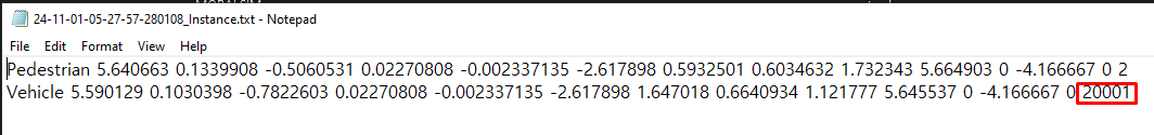
For objects with more than 2 bounding boxes, unique IDs are assigned as follows:
Pedestrian: The main person is assigned a unique ID in the standard unique ID assignment rule.
Vehicle: For composite objects (e.g., a 2-wheeled vehicle with a pedestrian), the main person’s unique ID is multiplied by 10,000, with increments of +1 for each additional related object.
The storage location is the same as described for the
binfile, under SaveFile/SensorData/LIDAR_*, with the file name being determined by the date and time of saving.
2] { }_instance_8Points.txt

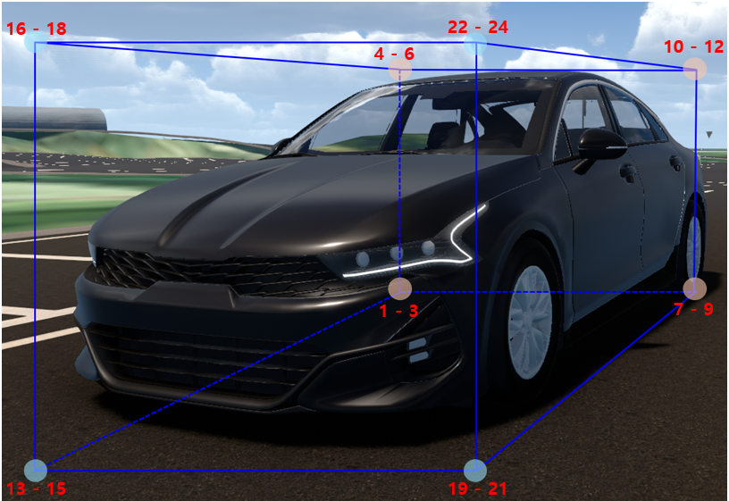
8 Points of 3D Bounding Box
The information for each value that consists of the ground truth data of the 3D Bounding Box detected by the LiDAR sensor is as follows:
0: The name of the class that is surrounded by the 8 corner points of the 3D BBox (rectangular cuboid shape).
1-3: left_down_back_x, left_down_back_y, left_down_back_z of the 3D BBox (unit: m)
Coordinates of the bottom-left rear corner of the 3D BBox in x, y, z.
4-6: left_up_back_x, left_up_back_y, left_up_back_z of the 3D BBox (unit : m)
Coordinates of the top-left rear corner of the 3D BBox in x, y, z.
7-9: right_down_back_x, right_down_back_y, right_down_back_z of the 3D BBox (unit : m)
Coordinates of the bottom-right rear corner of the 3D BBox in x, y, z.
10-12: right_up_back_x, right_up_back_y, right_up_back_z of the 3D BBox (unit : m)
Coordinates of the top-right rear corner of the 3D BBox in x, y, z.
13-15: left_down_front_x, left_down_front_y, left_down_front_z of the 3D BBox (unit : m)
Coordinates of the bottom-left front corner of the 3D BBox in x, y, z.
16-18: left_up_front_x, left_up_front_y, left_up_front_z of the 3D BBox (unit : m)
Coordinates of the top-left front corner of the 3D BBox in x, y, z.
19-21: right_down_front_x, right_down_front_y, right_down_front_z of the 3D BBox (unit : m)
Coordinates of the bottom-right front corner of the 3D BBox in x, y, z.
22-24: right_up_front_x, right_up_front_y, right_up_front_z of the 3D BBox (unit : m)
Coordinates of the top-right front corner of the 3D BBox in x, y, z.
25-27: Roll (rotation about the x-axis), Pitch (rotation about the y-axis), and Yaw (rotation about the z-axis) of the 3D Bounding Box (unit: radians).
These values represent the rotation angles of the object coordinate system calculated based on the LiDAR coordinate system.
28: Relative distance from the sensor to the object (unit: m).
29-31: Relative velocity of the object with respect to the sensor in the x, y, and z directions (unit: m/s).
32: Unique ID of the detected object.
For objects with more than 2 bounding boxes, unique IDs are assigned as follows:
Pedestrian: The main person is assigned a unique ID in the standard unique ID assignment rule.
Vehicle: For composite objects (e.g., a 2-wheeled vehicle with a pedestrian), the main person’s unique ID is multiplied by 10,000, with increments of +1 for each additional related object.
The storage location is the same as described for the
binfile, under SaveFile/SensorData/LIDAR_*, with the file name being determined by the date and time of saving.

Camera Sensor Data
RGB Image
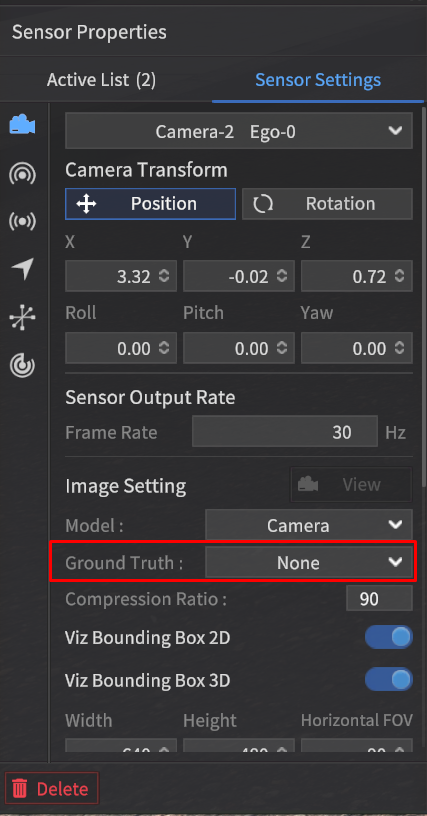
When a camera is spawned on the Ego vehicle and the Ground Truth setting is configured to Intensity, the detection data will be generated in RGB format.
File Format: *.png file
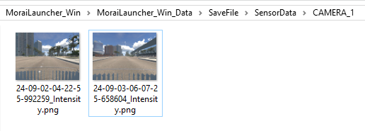
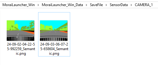
Using the sensor capture mode, the detection data will be saved at the path {Simulator Installation Path}/MoraiLauncher_Win/MoraiLauncher_Win_Data/SaveFile/SensorData/CAMERA_*.
The file names will be determined by the date and time when the images are saved.
Semantic Segmentation Image
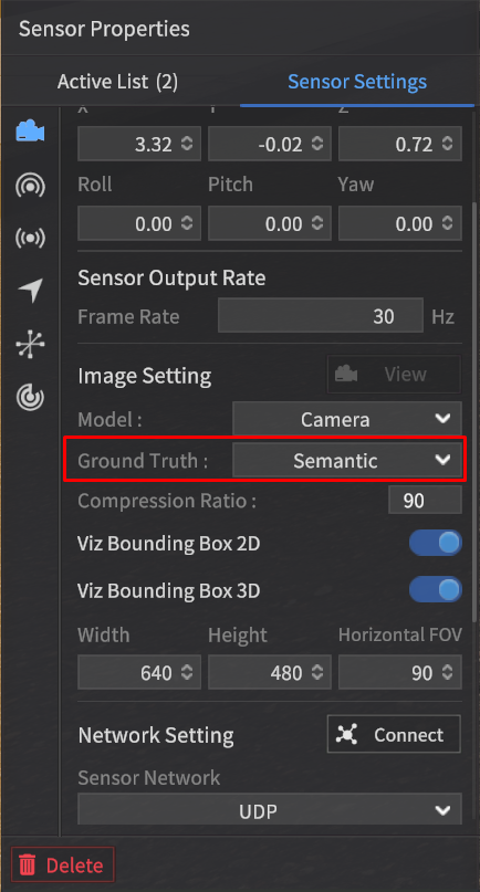
When the Ground Truth option is set to Semantic in the camera settings, image data detected using the Semantic Segmentation method will be generated.
File Format: *.png file
The storage location and file naming convention for Semantic Segmentation images are the same as for RGB images.
Labeling Color Map
The data detected using the Semantic Segmentation method is composed of RGB values for each class, where similar objects like vehicles, pedestrians, and lanes are classified together.
This classification follows the labeling color map provided, which assigns specific RGB values to each class, making it easy to visually distinguish between object types in the segmented image.
The LiDAR Semantic Value is calculated using the formula:
(LiDAR Semantic Value) = Rounds((R + G + B) / 3)
* (Exception 1) : Sky is not detected by LiDAR, so no value is assigned.
** (Exception 2): Since the calculated value for Road Sign is the same as Asphalt, the Road Sign is assigned a value of 128 by adding 1 to the result.
*** (Exception 3): Vehicles as obstacles are classified as Vehicle instead of Obstacle.
*** (Exception 3.1): A two-wheeled vehicle spawned as an obstacle in the simulator, is classified as a Vehicle if a person is onboard, and as an Obstacle if there is no rider.
Sensor type | Camera | 3D LiDAR | |||
Object | Class | R | G | B | Rounds((R + G + B) / 3) |
Vehicle | Vehicle | 255 | 2 | 2 | 86 |
Sedan | 255 | 60 | 60 | 125 | |
SUV | 255 | 75 | 75 | 135 | |
Truck | 255 | 90 | 90 | 145 | |
Bus | 255 | 105 | 105 | 155 | |
Van | 255 | 120 | 120 | 165 | |
Wagon | 255 | 135 | 135 | 175 | |
MPV | 255 | 150 | 150 | 185 | |
Pedestrian | Pedestrian | 98 | 2 | 255 | 118 |
Obstacle*** | Obstacle | 236 | 255 | 2 | 164 |
Road | Asphalt | 127 | 127 | 127 | 127 |
White Lane | 255 | 255 | 255 | 255 | |
Yellow Lane | 255 | 255 | 0 | 170 | |
Blue Lane | 0 | 178 | 255 | 144 | |
Crosswalk | 76 | 255 | 76 | 136 | |
Stop Line | 255 | 0 | 0 | 85 | |
Road Sign | 204 | 127 | 51 | 128** | |
Map Object | Traffic Light | 255 | 74 | 240 | 190 |
Traffic Sign | 99 | 48 | 250 | 132 | |
Sidewalk | 255 | 102 | 30 | 129 | |
Standing OBJ | 113 | 178 | 37 | 109 | |
Building | 153 | 255 | 51 | 153 | |
Road Edge | 178 | 178 | 178 | 178 | |
ETC | Sky | 0 | 255 | 255 | X* |
ETC | 23 | 2 | 6 | 10 | |
Ego Vehicle | 0 | 0 | 0 | 0 | |
The class names listed in the table are used for object classification purposes and are unrelated to the class values in 2D/3D BBOX data.
Object Categories:
Vehicle : Vehicles which can be spawned in the simulator.
Pedestrian : Pedestrians, bicycles, and any objects with a person on board.
Obstacle : Objects which can be spawned in the simulator.
Road : Road-related markings that are part of the map by default.
Map Object : Objects that are part of the map by default.
ETC : Miscellaneous objects, including the sky.
Ego Vehicle: The Ego-vehicle which the sensor spawned on it ( ⚠️ Multi Ego-vehicle is not applicable).
Labeling Color Map Rules:
LiDAR Semantic Value: This is calculated by rounding the integer value of the average of the Camera's RGB values.
For Vehicle, Pedestrian, and Obstacle objects:
If not classified into a specific subclass, a default value is assigned.
If classified into a detailed subclass, the corresponding specific value is assigned based on the object type.
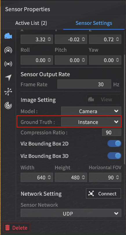
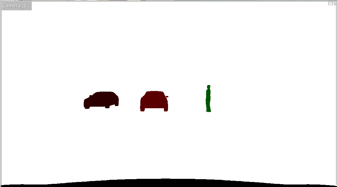
Instance Image
When the Ground Truth option in the camera settings is set to Instance, the captured image will be labeled according to Instance labeling.
This means each detected object, such as vehicles, pedestrians, or obstacles, will be assigned a unique identifier, allowing the system to distinguish between individual objects in the scene.
File Format: *.png file
The instance-labeled image assigns different pixel values even within the same class, allowing the differentiation of individual IDs within the class.
2D Bounding Box
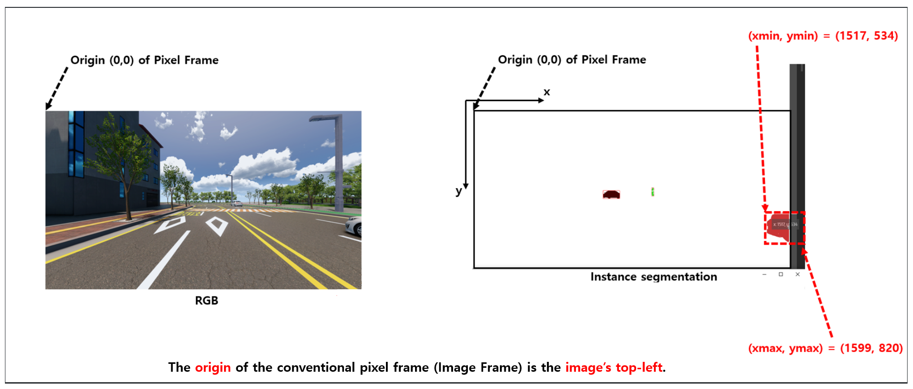
The 2D Bounding Box (2D BBox) is a rectangular ground truth data that surrounds objects detected by the camera sensor, representing the position of target objects.
The position coordinates of the target object consist of four values: the top-left (Min) x, y and bottom-right (Max) x, y in the pixel coordinate system.
For example, the coordinate information for a detected vehicle object from the camera sensor would include the top-left (Min) x, y and bottom-right (Max) x, y values in the pixel coordinate system.
Detection Data Format
The 2D Bounding Box (BBox) data is generated as a text file along with the instance image when the GT type is set to "Instance" during capture.
The data structure of the 2D Bounding Box (2D BBox) has been updated as follows:
It now consists of 7 data points, with the addition of Instance Color (RGBA) to the existing 6 data fields. For each object, the structure is:
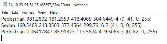
{Object Tag Name} + {Min x, y values (top-left corner in pixel coordinates)} + {Max x, y values (bottom-right corner in pixel coordinates)} + Object's Unique ID + Instance Color (RGBA)
2D BBOX Expression Value Definition (unit : pixels).
2D_BBOX_Xmin : X-coordinate of the top-left corner of the 2D bounding box.
2D_BBOX_Ymin : Y-coordinate of the top-left corner of the 2D bounding box.
2D_BBOX_Xmax : X-coordinate of the bottom-right corner of the 2D bounding box.
2D_BBOX_Ymax : Y-coordinate of the bottom-right corner of the 2D bounding box.
File Format: txt file
Data Structure: It consists of a total of 7 data points (for each object).
Index | Data | Note |
|---|---|---|
1 | Class Name of detected Object | Same as the Tag in the Class definition |
2 | 2D_BBOX_Xmin |
|
3 | 2D_BBOX_Ymin |
|
4 | 2D_BBOX_Xmax |
|
5 | 2D_BBOX_Ymax |
|
6 | Unique ID of the detected Object | The unique ID assigned to the object in MORAI SIM. For objects with more than 2 bounding boxes:
|
7 | Instance Color (RGBA) | The color assigned to the object in the instance.png file. The RGB 3 channels indicate the Semantic color (the color assigned to the object's tag in the Class definition), while the A (alpha) channel represents the unique ID of the object within the Semantic class group. |
Example:
Detectable Target Objects: Vehicle, Pedestrian, Obstacle, Traffic Light.
3D Bounding Box
The system provides the function to generate 3D Bounding Box (BBox) data for objects detected by the camera sensor.
A 3D Bounding Box (BBox) represents the ground truth data in the form of a three-dimensional rectangular prism surrounding the objects detected by the camera sensor, indicating the positions of target objects.
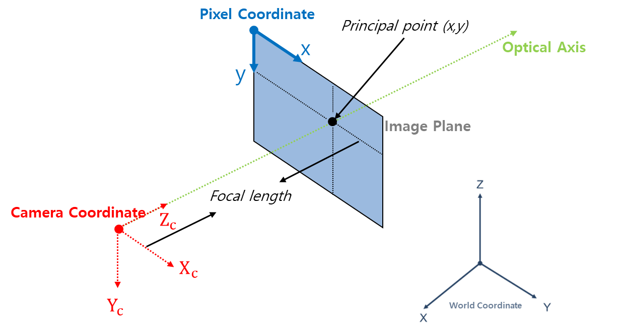
The positional coordinate information of the target objects is composed of the eight vertexes of the 3D BBox, referenced in the Camera coordinate system.
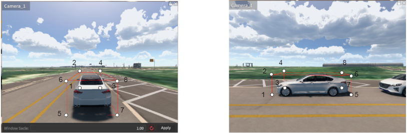
The camera coordinate system for one point is defined as follows, with the axis in the direction the camera faces, referred to as the Optical Axis, and represented by the coordinates (x, y, z).
X : Right
Y : Down
Z : Forward (=Optical Axis)
Detection Data Format
When the Ground Truth (GT) type is set to Instance during capture, the 3D Bounding Box data is generated as a text file along with the corresponding Instance image.
3D BBOX Expression Value Definition (unit : m)
3D_BBOX_X1, 3D_BBOX_Y1, 3D_BBOX_Z1 : The X, Y, and Z coordinates of Point 1 in the Camera coordinate system.
3D_BBOX_X2, 3D_BBOX_Y2, 3D_BBOX_Z2 : The X, Y, and Z coordinates of Point 2 in the Camera coordinate system.
3D_BBOX_X3, 3D_BBOX_Y3, 3D_BBOX_Z3 : The X, Y, and Z coordinates of Point 3 in the Camera coordinate system.
3D_BBOX_X4, 3D_BBOX_Y4, 3D_BBOX_Z4 : The X, Y, and Z coordinates of Point 4 in the Camera coordinate system.
3D_BBOX_X5, 3D_BBOX_Y5, 3D_BBOX_Z5 : The X, Y, and Z coordinates of Point 5 in the Camera coordinate system.
3D_BBOX_X6, 3D_BBOX_Y6, 3D_BBOX_Z6 : The X, Y, and Z coordinates of Point 6 in the Camera coordinate system.
3D_BBOX_X7, 3D_BBOX_Y7, 3D_BBOX_Z7 : The X, Y, and Z coordinates of Point 7 in the Camera coordinate system.
3D_BBOX_X8, 3D_BBOX_Y8, 3D_BBOX_Z8 : The X, Y, and Z coordinates of Point 8 in the Camera coordinate system.
3D_BBOX_X1, 3D_BBOX_Y1 : The X ,Y coordinates of Point 1 in the Image plane.
3D_BBOX_X2, 3D_BBOX_Y2 : The X ,Y coordinates of Point 2 in the Image plane.
3D_BBOX_X3, 3D_BBOX_Y3 : The X ,Y coordinates of Point 3 in the Image plane.
3D_BBOX_X4, 3D_BBOX_Y4 : The X ,Y coordinates of Point 4 in the Image plane.
3D_BBOX_X5, 3D_BBOX_Y5 : The X ,Y coordinates of Point 5 in the Image plane.
3D_BBOX_X6, 3D_BBOX_Y6 : The X ,Y coordinates of Point 6 in the Image plane.
3D_BBOX_X7, 3D_BBOX_Y7 : The X ,Y coordinates of Point 7 in the Image plane.
3D_BBOX_X8, 3D_BBOX_Y8 : The X ,Y coordinates of Point 8 in the Image plane.
File Format: txt file
Data Structure: It consists of a total of 77 data points (for each object).
Index | Label | Note |
|---|---|---|
1 | Class Name of detected Object | Same as the Tag in the Class definition. |
2 ~ 4 | 3D_BBOX_X1, Y1, Z1 | Based on the Camera coordinate System. |
5 ~ 7 | 3D_BBOX_X2, Y2, Z2 | Based on the Camera coordinate System. |
8 ~ 10 | 3D_BBOX_X3, Y3, Z3 | Based on the Camera coordinate System. |
11 ~ 13 | 3D_BBOX_X4, Y4, Z4 | Based on the Camera coordinate System. |
14 ~ 16 | 3D_BBOX_X5, Y5, Z5 | Based on the Camera coordinate System. |
17 ~ 19 | 3D_BBOX_X6, Y6, Z6 | Based on the Camera coordinate System. |
20 ~ 22 | 3D_BBOX_X7, Y7, Z7 | Based on the Camera coordinate System. |
23 ~ 25 | 3D_BBOX_X8, Y8, Z8 | Based on the Camera coordinate System. |
26 ~27 | 3D_BBOX_X1, Y1 | Based on the Image plane. |
28 ~ 29 | 3D_BBOX_X2, Y2 | Based on the Image plane. |
30 ~ 31 | 3D_BBOX_X3, Y3 | Based on the Image plane. |
32 ~ 33 | 3D_BBOX_X4, Y4 | Based on the Image plane. |
34 ~ 35 | 3D_BBOX_X5, Y5 | Based on the Image plane. |
36 ~ 37 | 3D_BBOX_X6, Y6 | Based on the Image plane. |
38 ~ 39 | 3D_BBOX_X7, Y7 | Based on the Image plane. |
40 ~41 | 3D_BBOX_X8, Y8 | Based on the Image plane. |
42 | Unique ID of detected Object | The unique ID assigned to the object in MORAI SIM. For objects with more than 2 bounding boxes:
|
43 | Instance Color (RGBA) | Same as the Instance Color in 2D BBOX. |
Example:

Detectable Target Object: Vehicle, Pedestrian, Obstacle
Depth Image
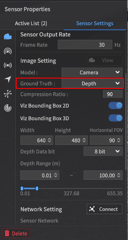
When the Ground Truth in the camera sensor settings is set to Depth, it detects the depth values of objects and generates a Depth image.
As the distance increases within the output range for Depth GT, the color approaches white.
Objects closer than the minimum distance are represented in black (0).
Objects farther than the maximum distance are also displayed in black (0).
When checking the Depth GT data using the View feature, it will be displayed as red pixels within the specified Depth Data bit range ([0, 28] or [0, 216]), as shown in the screen below.
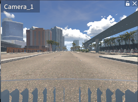
RGB Image
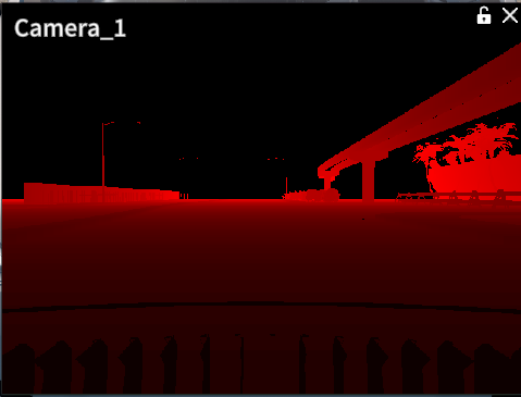
Depth Image (Camera View in the Drive Simulator)
As shown below, the Depth GT can be generated as an image file (.png) using the sensor capture feature.
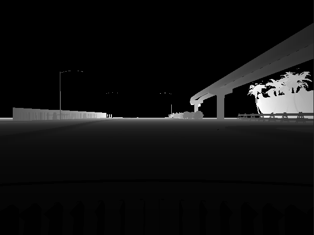
Depth Image (saved in png after sensor capture mode)
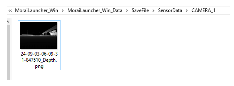
File Format: .png file
The detection data will be saved at the path SaveFile/SensorData/CAMERA_*, and the file names will be determined by the date and time when the images are saved.
Previously, Depth GT was generated only as an 8-bit image.
However, the camera sensor's depth image generation function has been enhanced, allowing it to produce an 8-bit image when set to 8 bits and a 16-bit image when set to 16 bits.
GPS Data
File Format: txt file
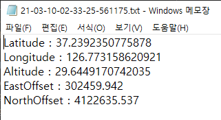
Data Structure of the GPS data is as follows:
1: Latitude (unit: deg)
2: Longitude (unit: deg)
3: Altitude (unit: m)
4: EastOffset (unit : m), * Offset value in the eastern direction relative to the UTM map origin (a fixed constant value for each map).
5: NorthOffset (unit : m), * Offset value in the northern direction relative to the UTM map origin (a fixed constant value for each map).
The data will be saved at the path SaveFile/SensorData/GPS_*, and the file names will be determined by the date and time when the data are saved.
IMU Data
File Format: txt file
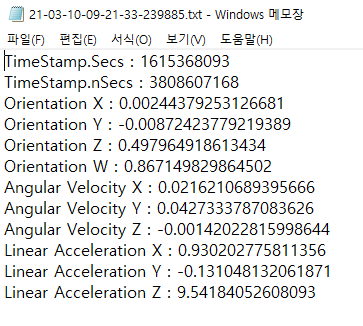
Data Structure of the IMU data is as follows:
1-2 : TimeStamp. 1 is in seconds, and 2 is in nanoseconds.
3-6 : Orientation X, Y, Z, W. The sensor's orientation is expressed in quaternion format.
7-9 : Angular Velocity X, Y, Z. Components of angular velocity based on the X, Y, and Z axes (unit: rad/s).
10-12 : Linear Acceleration X, Y, Z. Components of acceleration based on the X, Y, and Z axes (unit: m/s²).
The data will be saved at the path SaveFile/SensorData/IMU_*, and the file names will be determined by the date and time when the data are saved.
A feature has been developed to calculate acceleration values based on the IMU's position, enhancing the sophistication of the IMU sensor data.
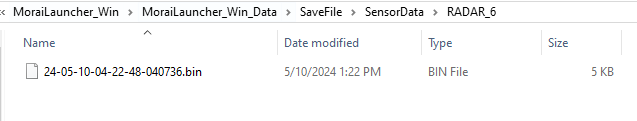
Radar Data
File Format: bin file
Data Structure: Within the bin file, the index information of each Radar measurement, along with its position, azimuth, velocity information, and RCS (amplitude) values, is saved in a continuous format without spaces. The origin is based on the position where the Radar is mounted.
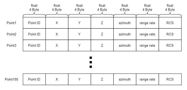
0: point_id
2-4: Position by x, y, z.
5: azimuth
6: range rate
7 : rcs
For Python users, you can load the float32 variables using the numpy library’s fromfile function as shown below:
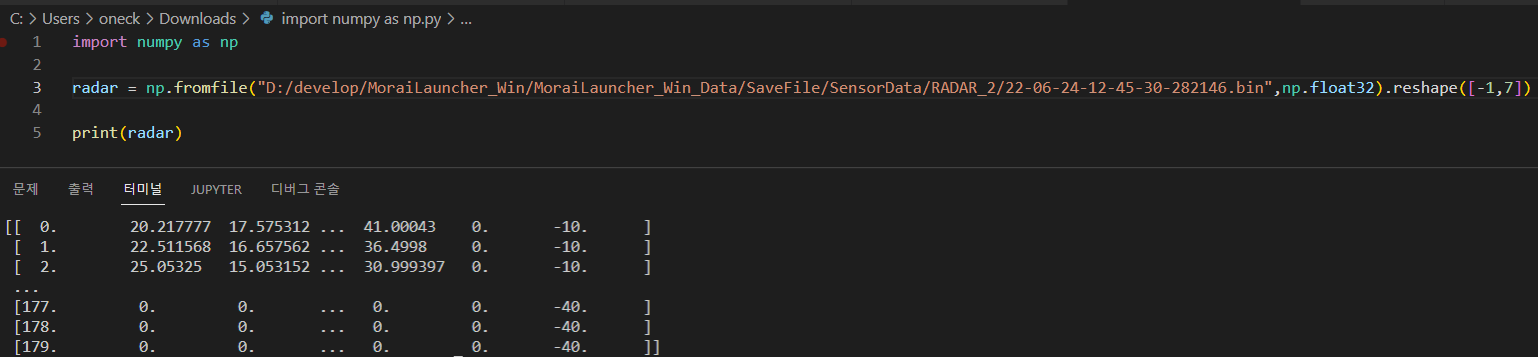
The storage location is SaveFile/SensorData/RADAR_*, where the * corresponds to the filename, which is determined by the date and time the point cloud was saved.