ROS2 Data Sync Example
This page walks the user through a full step-by-step process to combine sensor models and network connection features in MORAI SIM to build a sensor stream to an external node using ROS2.
Unlike MORAI SIM’s UDP and ROS implementations, ROS2 is only supported through external code for evaluation and academia users.
Native ROS2 support is coming with MORAI SIM V2 slated for release in Q2 2026.
Before we start: Supported versions
MORAI SIM currently supports the following versions of ROS2. Please contact your account manager or any of our channels if you would like to be notified when we update support for newer versions.
ROS 2 Version | Supported? | Released |
|---|---|---|
Foxy (Ubuntu 20.04) |
| 2022 |
Galactic (Ubuntu 20.04) |
| 2022 |
Humble (Ubuntu 22.04) |
| 2025.12 |
Jazzy(Ubuntu 24.04) |
| 2026.1 |
Step 1: Setting up the test environment
This example uses a custom bridge script that uses a gRPC connection with MORAI SIM to relay signals from the simulation to a ROS2 network.
The test environment can be on:
a single Ubuntu machine set to a local network connection (e.g.
127.0.0.01)a single Windows machine using WSL2 or a virtual machine running Ubuntu
on separate machines connected by an ethernet cable
on a virtual machine either located within the local machine or in the cloud
Unlike a our other examples, setting up a ROS2 environment is even more involved with multiple steps. Please refer to this separate dedicated startup guide: Developer Setup for ROS2. For more resources, some good external references are:
Step 2: Preparing the simulator
Follow the steps below to receive sensor data transmitted by the simulator via ROS. If successful, it will be possible to verify each sensor's output stream in a separate visualizer.
1. Place sensors onto the vehicle. To stream sensor data from the simulator to any external sources, we must first place said sensors onto the vehicle to instantiate them.
The following steps are the same as those found in the Get Started and Basic Controls chapters in this manual.
Press the F3 key (or select Edit >> Sensor >> Edit Sensor Mode from the main menu bar)
Select a sensor from the selection box that should appear in the top left corner.
Shift + click to place the sensor onto vehicle
The sensor model should auto-snap to the surface of the vehicle
Alt + click to remove sensors (if necessary)
For this example, place one of each sensor: camera, GPS, IMU, 3D lidar. Note that where you place sensors in this example is not important, but it is recommended to place them in reasonable locations (i.e. in front of or on top of the vehicle model)
2. Set up the sensor network in the simulator. Set up each sensor’s network connection settings in the Sensor Properties tab (see example in screenshot below) and click Connect.
For ROS2 connections, as a separate gRPC connection is used to relay data from the simulator, the specific settings are unimportant. Just make sure the port numbers do not overlap as the UI will refuse to connect the sensor.
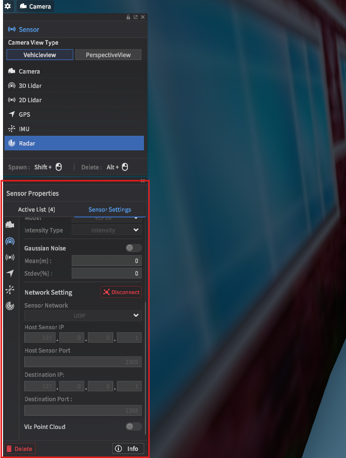
In sensor placement mode, network settings are located under the sensor settings tab
Step 3: Connecting to MORAI SIM with the ROS2 bridge
Preparing the simulator and the sensor config has been explained in this section ROS2 Data Sync Example | Step-2:-Preparing-the-simulator. Here it is explained how the data communication between Windows and WSL via a ROS2 bridge can be setup.
Downloads (these will be moved to our Github in 2026)
morai_ros2_bridge.zip (<-- for galactic / other versions available here)
Testing the connection (example here: ego vehicle data and image stream of camera sensor)
Two JSON files are key configuration files that are required to make the connection between MORAI SIM and the ROS2 stack work
The sensor config JSON file: contains the information required by MORAI SIM to instantiate and initialize the sensor models -- is located in your MORAI SIM install (windows) -- attached example is
sensor_1cam.jsonThe ROS2 config JSON file: contains info on connecting MORAI SIM related sensor model variables to their ROS2 counterparts -- should be located in your Ubuntu system -- attached example is
morai_sim_sensor_1cam.json
Set up a preconfigured sensor config JSON file
this file lives under
MoraiLauncher_Win_Data/SaveFile/Sensor/[MORAI SIM Version=24.R2.H2]/can be a sensor file set up yourself with the help of MORAI UI, as long as the name coincides with the
sensorConfigFileNamevariable in your ROS2 config JSON and the sensor setup is reflected in the ROS2 JSON file
Connect the
connector.pyscript with your ROS2 config JSONMove the ROS2 config JSON file to the same folder you have your
connector.pyscript (or adjust the path settings in the python script)Make sure the
SensorInterface.sensorConfigFileNamevariable in your ROS2 config JSON matches the name of your sensor config JSON file
Run MORAI SIM
sometimes preexisting network setting configurations may cause issues - reset these by deleting NetworkInfo JSON files that are in
MoraiLauncher_Win_Data_SaveFile/Network/[MORAI SIM Version]/Do not perform any usual setup actions in MORAI SIM
In wsl (terminal #1), run the ROS2 bridge executable morai_ros2_bridge
- BASH
source /opt/ros/<replace with your ROS2 distro>/setup.bash
source ~/ros2_ws/install/setup.bash
~/morai_ros2_bridge --addr <your Windows IP address>
In a new wsl window (terminal #2), run the
connector.pyscript- BASH
source /opt/ros/<replace with your ROS2 distro>/setup.bash
source ~/ros2_ws/install/setup.bash
python3 ~/morai_ros2_connector/morai_sim_ros2_connector.py
You should now start seeing ROS2 nodes created and displayed in terminal #1
Additional steps (if the camera image is now showing correctly)
In wsl (terminal #3), run the following command to start an image_transport topic
ros2 run image_transport republish compressed raw --ros-args -r in/compressed:=/sensing/camera/traffic_light/image_raw -r out:=/sensing/camera/traffic_light/image_decompressedNote that topic names here are synced to the content in our ROS2 config JSON
Step 4: Subscribe and visualize ROS2 topics
We can subscribe to ROS2 topics via native ROS tools like rqt or RViz
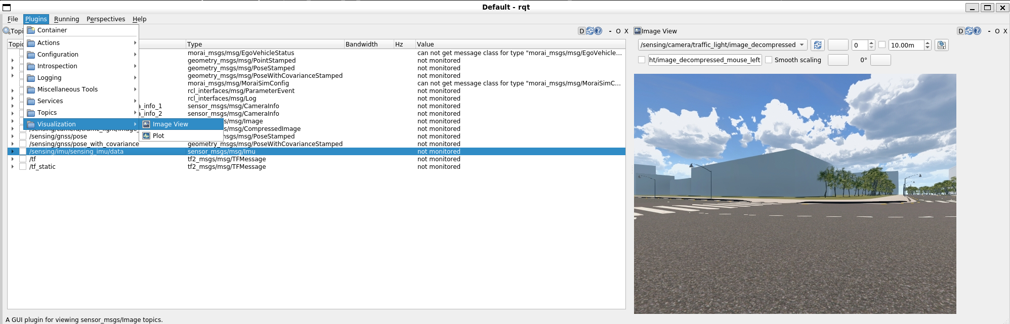
Example 1 – rqt:
In wsl (terminal #4), run
rqtA UI with a Topic Monitor should open up. If setup correctly the configured topics should be visible in the Topic Monitor and when selected a data stream should be visible
Subscribe to the newly created
image_decompressedtopic to check image data is being transmittedBy using a Visualization plugin it should also be possible to see the image stream
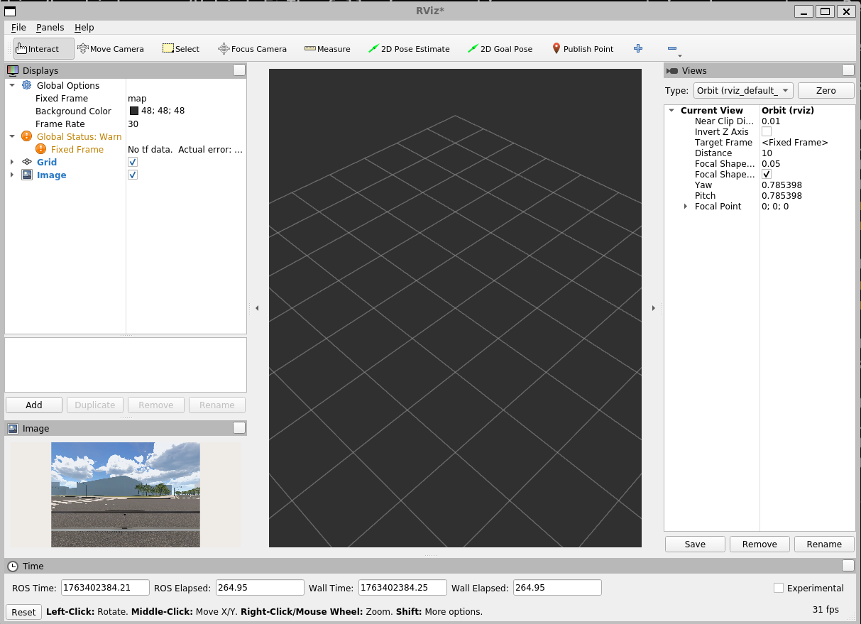
Example 2 – RViz2:
In wsl (terminal #5), run
rviz2Open the RViz UI, Click “Add” (buttom left) and “Create visualization” “By topic”
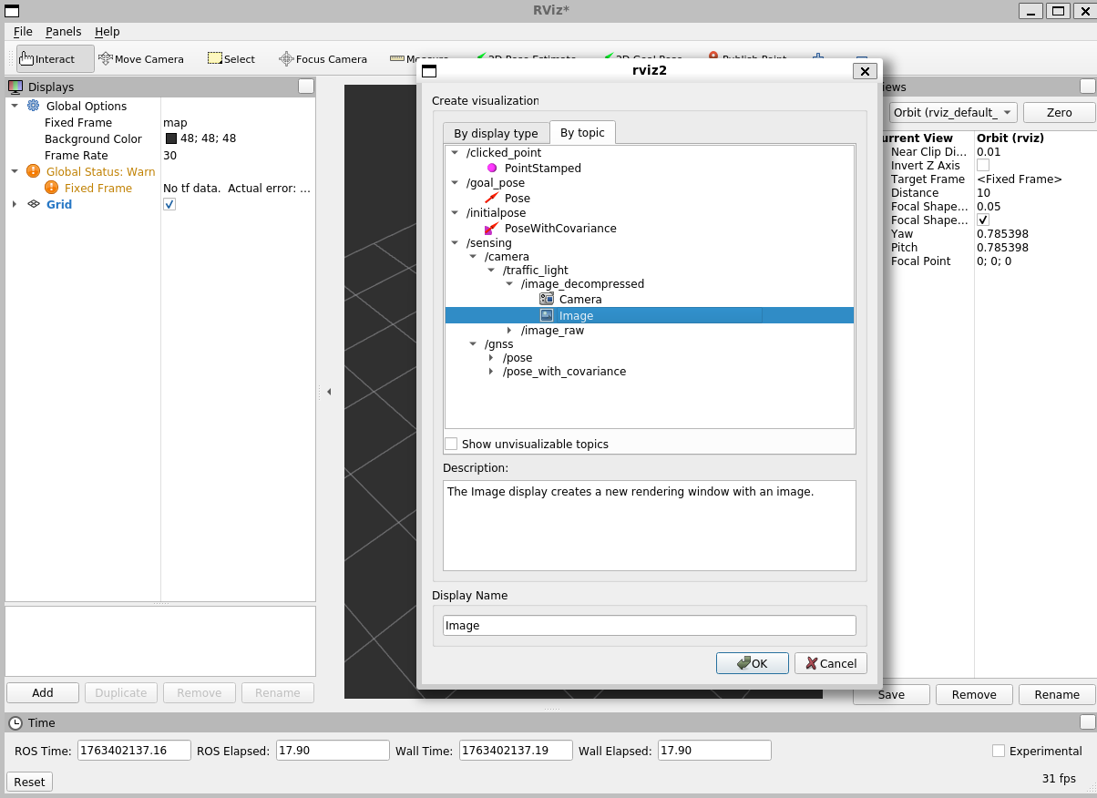
This should then visualize the data stream (e.g. an image in the bottom left)