
ROS Data Sync Example
This page walks the user through a full step-by-step process to combine sensor models and network connection features in MORAI SIM to build a sensor stream to an external node.
Step 1: Setting up the test environment
This example uses MORAI SIM’s ROS network features and associated UI to connect to a sample visualizer.
The test environment can be on:
a single machine set to a local network connection (e.g.
127.0.0.01)on separate machines connected by an ethernet cable
on a virtual machine either located within the local machine or in the cloud
Unlike a simple TCP/UDP connection, setting up a ROS environment is an involved process. Please refer to our documentation Quick Start Guide for ROS, or refer to the ROS wiki https://wiki.ros.org/ for more set-up information.
Before moving on to step 2, the roscore should be initialized with the correct setup scripts sourced.
Step 2: Preparing the simulator
Follow the steps below to receive sensor data transmitted by the simulator via ROS. If successful, it will be possible to verify each sensor's output stream in a separate visualizer.
1. Place sensors onto the vehicle. To stream sensor data from the simulator to any external sources, we must first place said sensors onto the vehicle to instantiate them.
The following steps are the same as those found in the Get Started and Basic Controls chapters in this manual.
Press the F3 key (or select Edit >> Sensor >> Edit Sensor Mode from the main menu bar)
Select a sensor from the selection box that should appear in the top left corner.
Shift + click to place the sensor onto vehicle
The sensor model should auto-snap to the surface of the vehicle
Alt + click to remove sensors (if necessary)
For this example, place one of each sensor: camera, GPS, IMU, 3D lidar. Note that where you place sensors in this example is not important, but it is recommended to place them in reasonable locations (i.e. in front of or on top of the vehicle model)
2. Set up the sensor network in the simulator. Set up each sensor’s network connection settings in the Sensor Properties tab (see example in screenshot below) and click Connect.
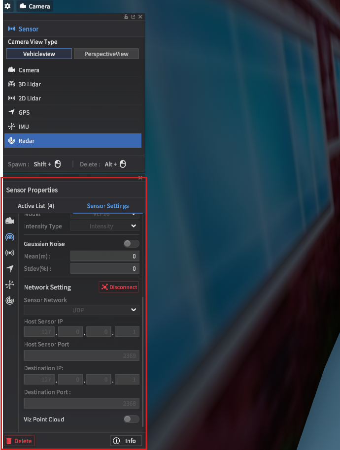
In sensor placement mode, network settings are located under the sensor settings tab
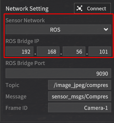
Use the drop-down menu to switch to ROS mode
As MORAI SIM was built for Windows machines in mind, ROS connections initially connect to a separate rosbridge. If your ROS environment is running on a different machine, use the IP address of your machine, else, simply use 127.0.0.1.
3. Check ROS connections have been made properly. After configuring each sensor network to ROS communication and clicking Connect, check the logs for the message Client connected in the rosbridge terminal, as shown below.
Since we are using four different sensor models for this example, the terminal should read 4 clients total.
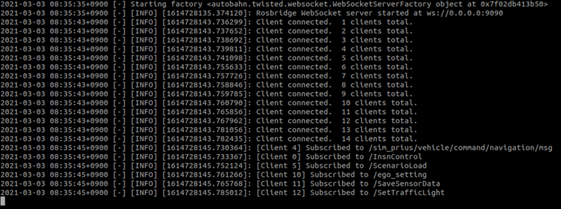
Example console output for the rosbridge connector
Step 3: Verification using an external visualizer
1. Set up the external visualizer. Download our python-based test visualizer UI from GitHub.
Follow the instructions in the readme to set up the visualizer - you may need prior experience in python.
We recommend using anaconda, poetry, uv or similar python development environment management systems to keep python libraries from clashing.
The UI is set by default for UDP connections – use the drop-down menu to switch configurations for ROS, and ensure the rostopic names and message type options match the installed ROS environment.
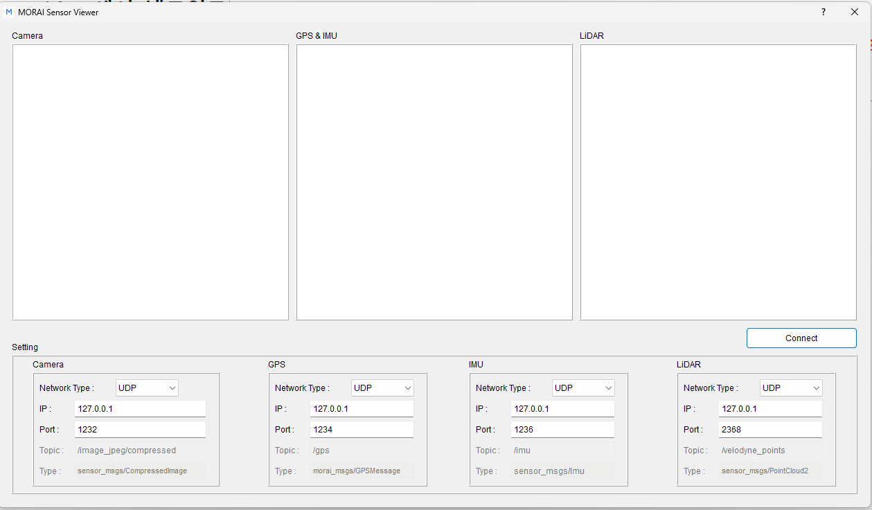
Our external visualizer for this example
2. Confirm the sensor data can stream to the visualizer. Upon clicking the Connect button in the visualizer, each of the sensor screens should stream data from the simulator. Try moving around the scene with your vehicle - the sensor data streams should update accordingly.
-20230417-083542.png?inst-v=8346d6e7-5ad5-451f-b374-ed704e723b6e)
Troubleshooting with rqt. In case the steps above do not result in the visualizer working correctly, it is recommended to use established tools to check the network settings have been made correctly.
In a separate terminal, source the setup scripts as usual and call rqt to bring up the rqt interface. rqt is included in most ROS installs and contains tools to help analyze the ROS environment. Select the topic monitor tool and check to see if your rostopics are streaming data and showing expected values. Also use the Image visualizer to independently verify that the Camera sensor model output is showing correctly.
Congratulations, you have finished this ROS networking example.