
Sensor Coordinate Systems
This section describes the coordinate system for each sensor in MORAI simulator and how to verify the sensor output data.
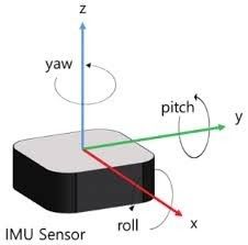
IMU Coordinate System
Measure the values of a 6-degree-of-freedom system.
( X, Y, Z, roll, pitch, yaw )
IMU Sensor Output Data
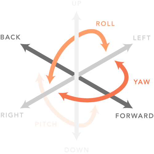
linear_acceleration
X : X-axis acceleration in IMU sensor (Forward +, Backward -)
Y : Y-axis acceleration in IMU sensor (Left +, right -)
Z : Z-axis acceleration in IMU sensor (UP +, Down -)
angular_velocity
X : X-axis angular velocity in IMU sensor (Roll)
Y : Y-axis angular velocity in IMU sensor (Pitch)
Z : Z-axis angular velocity in IMU sensor (Yaw)
(CounterClockwise +, Clockwise -)
orientation
X : Quaternion X vector
Y : Quaternion Y vector
Z : Quaternion Z vector
w : Quaternion w vector
GPS Coordinate System
Follow UTM Coordinate system
UTM52N (WGS84)
EPSG:32652
+proj=utm +zone=52 +ellps=WGS84 +datum=WGS84 +units=m +no_defs
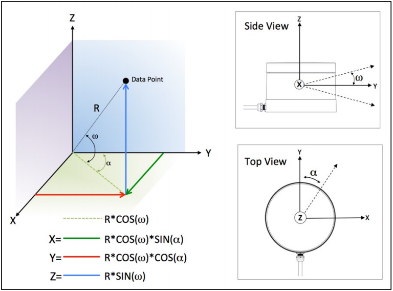
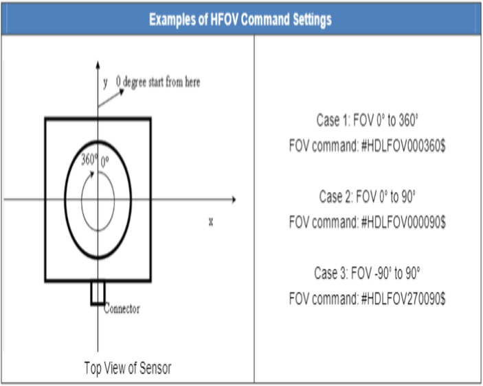
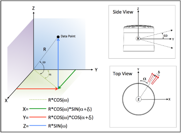
Velodyne LiDAR Coordinate System
Forward : y
Right : x
Up : z
Velodyne LiDAR Manual Information
< 16ch LiDAR >
< 32ch LiDAR >
< 64ch LiDAR >
< 128ch LiDAR >
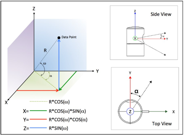
ROS Axis Orientation
Once you check the standard units of ROS in REP 103 (ROS Enhancement Proposals), you will know the basic units used in ROS. ( https://www.ros.org/reps/rep-0103.html#id14 )
Forward : x
Left : y
Up : z
Use ROS Velodyne_driver
When outputting data via ROS Velodyne_driver, it is represented in the default ROS coordinate system rather than the original Velodyne coordinate system. The Velodyne LiDAR coordinates change from (forward: y, right: x, up: z) to (forward: x, left: y, up: z).Comparison between Veloview and ROS RViz using the simulator.
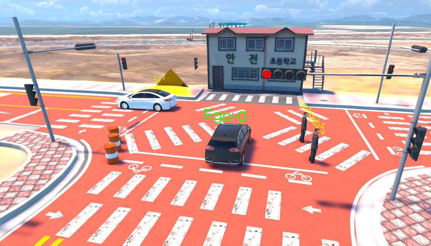
Simulator
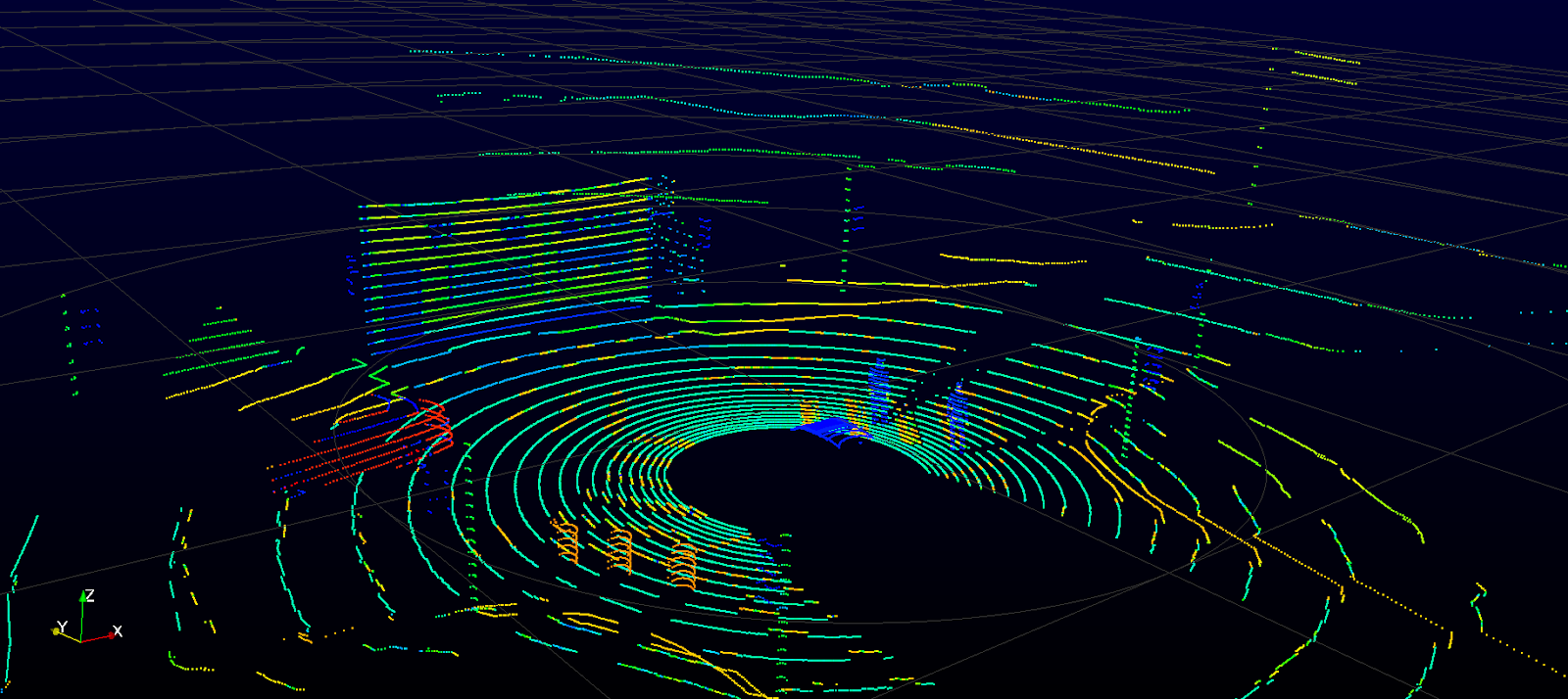
Veloview
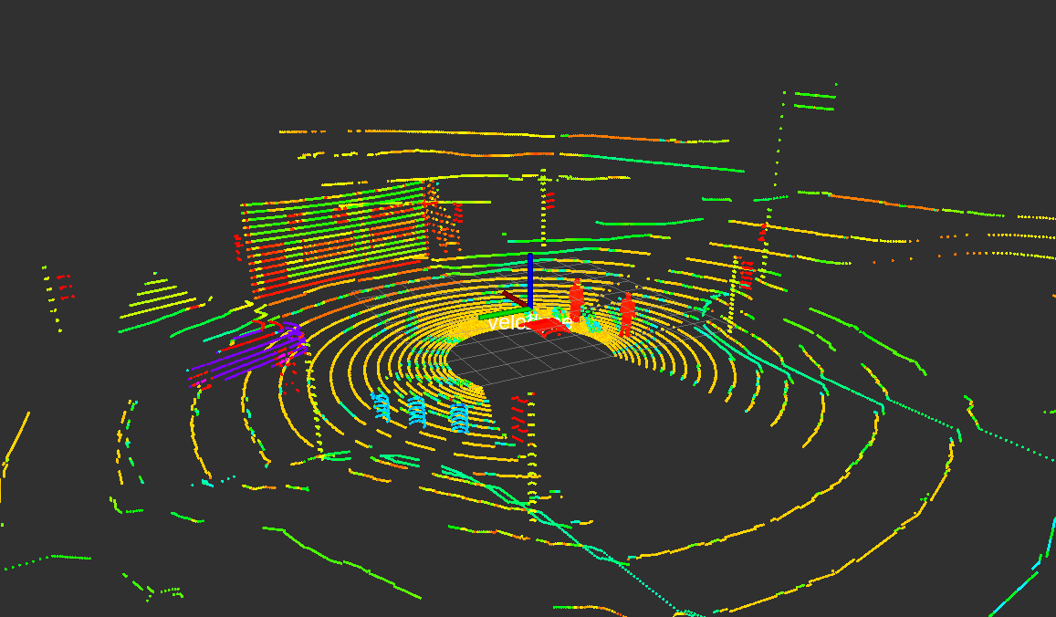
RViz
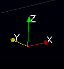
Veloview Axis
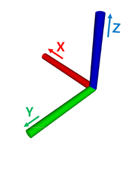
Rviz Axis