
Basic Features of Sensors
This section explains how to spawn and configure sensors (Camera, Lidar, GPS, IMU, Radar) provided by MORAI SIM: Drive.
Spawn & Delete Sensor
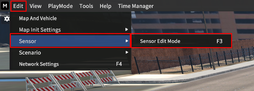
Go to Edit > Sensor > Sensor Edit Mode to open the Sensor Properties.
Select the desired sensor in the Sensor Properties, then press Shift + Mouse left-click to spawn the sensor on the vehicle.
You can confirm the active sensors in the Active List.
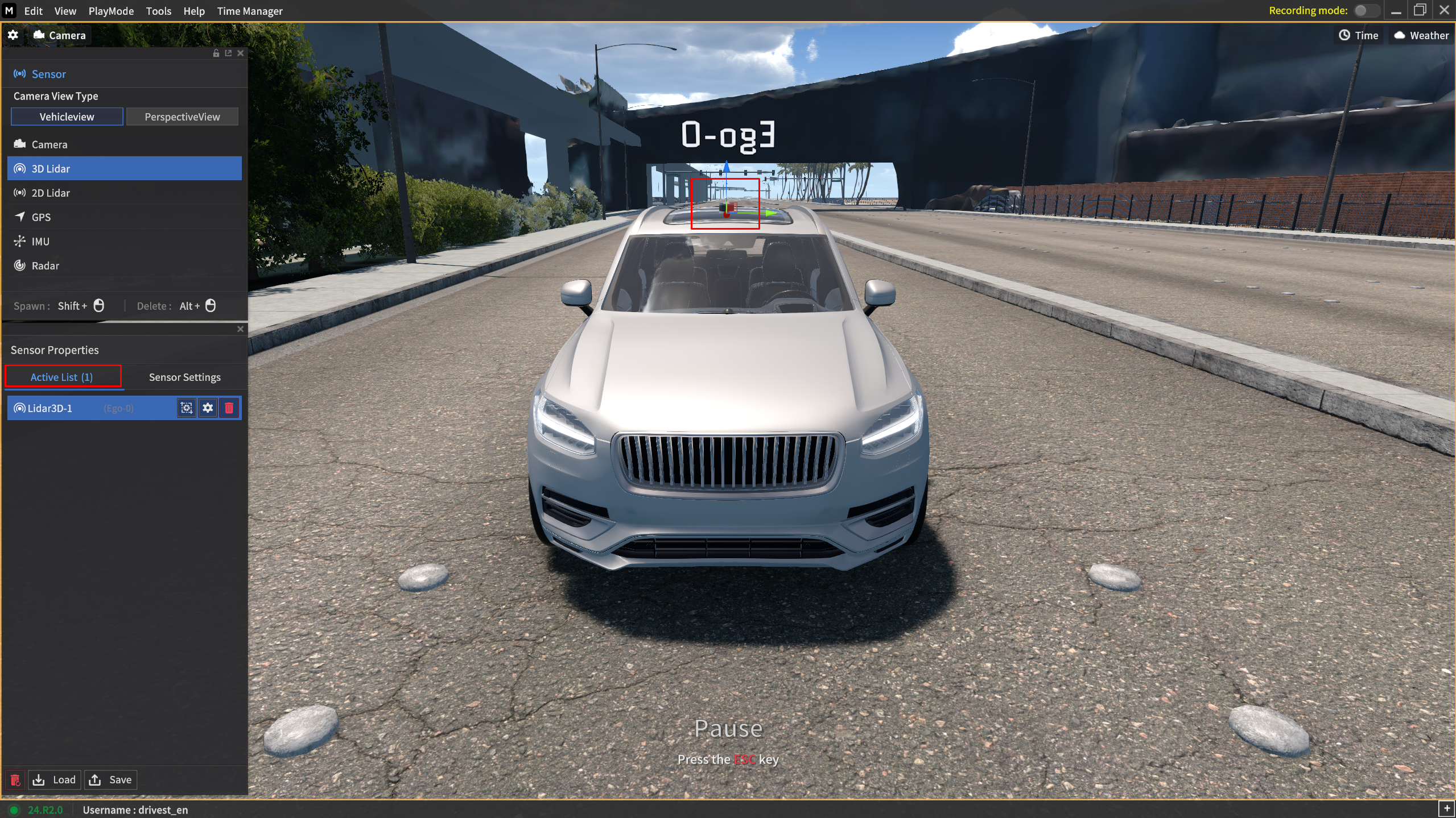
There are two ways to remove the active sensors as follows:
Click the trash bin icon in the Active List.
Press
Alt+Mouse left-clickto delete the active sensor you want to delete.
Sensor Settings UI
To access to the Sensor Settings, click ⚙️ icon for each sensor you spawned in the Active List.
Alternatively, click the icon that matches the sensor name in the left icon panel of the Sensor Settings.
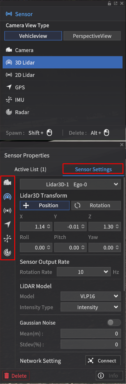
In the Sensor Settings, you can check and change the sensor's position, rotation, and specific parameters according to the sensor type.
Specific parameters for sensors are described in separate sections below.
Object data detected by the configured sensors can be immediately confirmed in the simulator using the “view function” specific to each sensor, as shown below.
Camera: View
GPS & IMU: Info
LiDAR: vizPath
Radar: Viz Radar Range
Sensor Network Setting
In the Network Setting under Sensor Settings, configure the sensor communication network to transmit the data detected by the sensors via ROS or UDP communication protocols.
Each sensor supports different types of communication, but for the same communication type, the configuration method is the same.
ROS
Set ROS Bridge IP/Port for ROS.
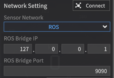
Regardless of the sensor, the setup method is the same for each communication type.
However, the communication messages differ for each sensor in the case of ROS communication.
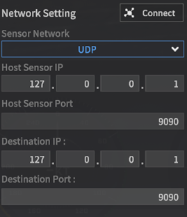
UDP
Set Host and Destination IP/Port for the transmission packet.
Viz Bounding Box 2D/ 3D
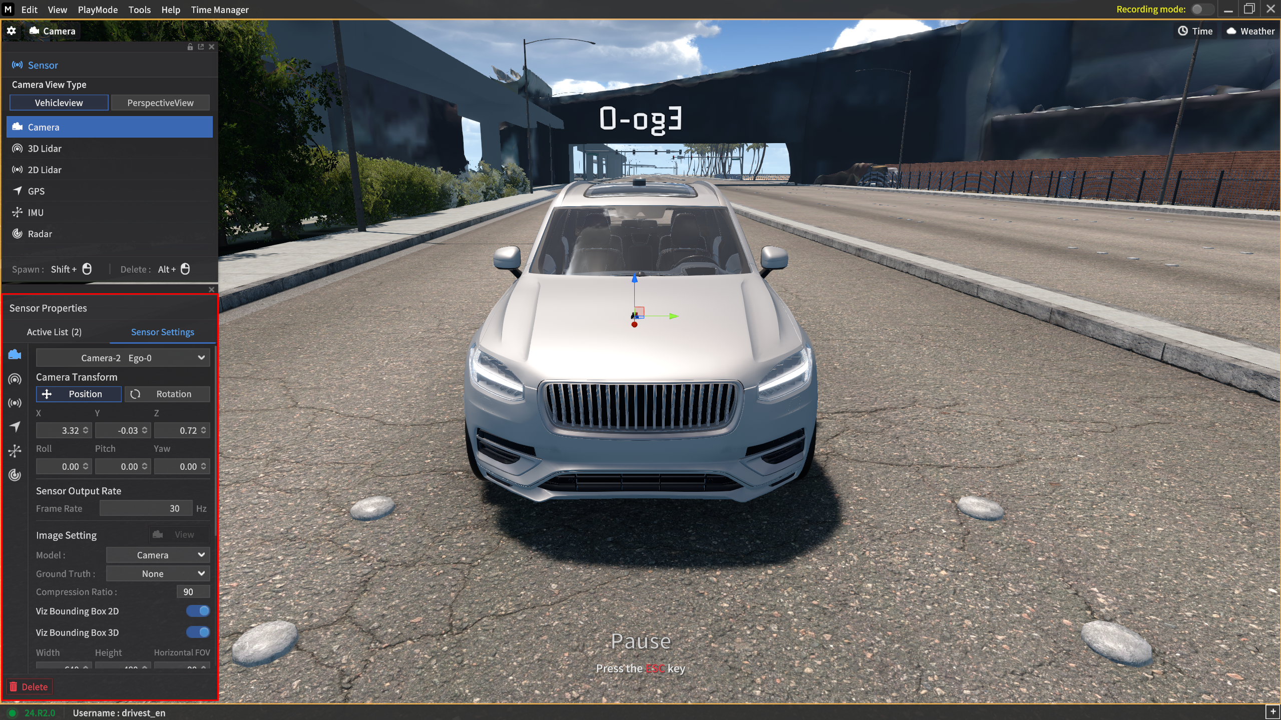
Viz Bounding Box 2D/3D feature has been added, allowing you to check the 2D/3D BBox of objects detected by the camera sensor in the simulator.
In the camera settings as shown below, you can activate the Viz Bounding Box 2D and 3D options, and click the View to display the 2D and 3D Bounding Boxes on the View screen.
Red-colored box: 2D Bounding Box
Blue-colored box: 3D Bounding Box
The Viz Bounding Box 2D and 3D options are unrelated to the 2D/3D BBox detection function that generates a text file when captured.
In other words, even if the Viz Bounding Box 2D and 3D options are disabled, you can still use the capture function in the camera sensor's Instance GT type to generate and save 2D/3D Bounding Box text information for objects.
When the Viz Bounding Box 2D and 3D options are enabled and the GT is set to None (RGB), the 2D/3D Bounding Boxes will be displayed as shown below in the View function.
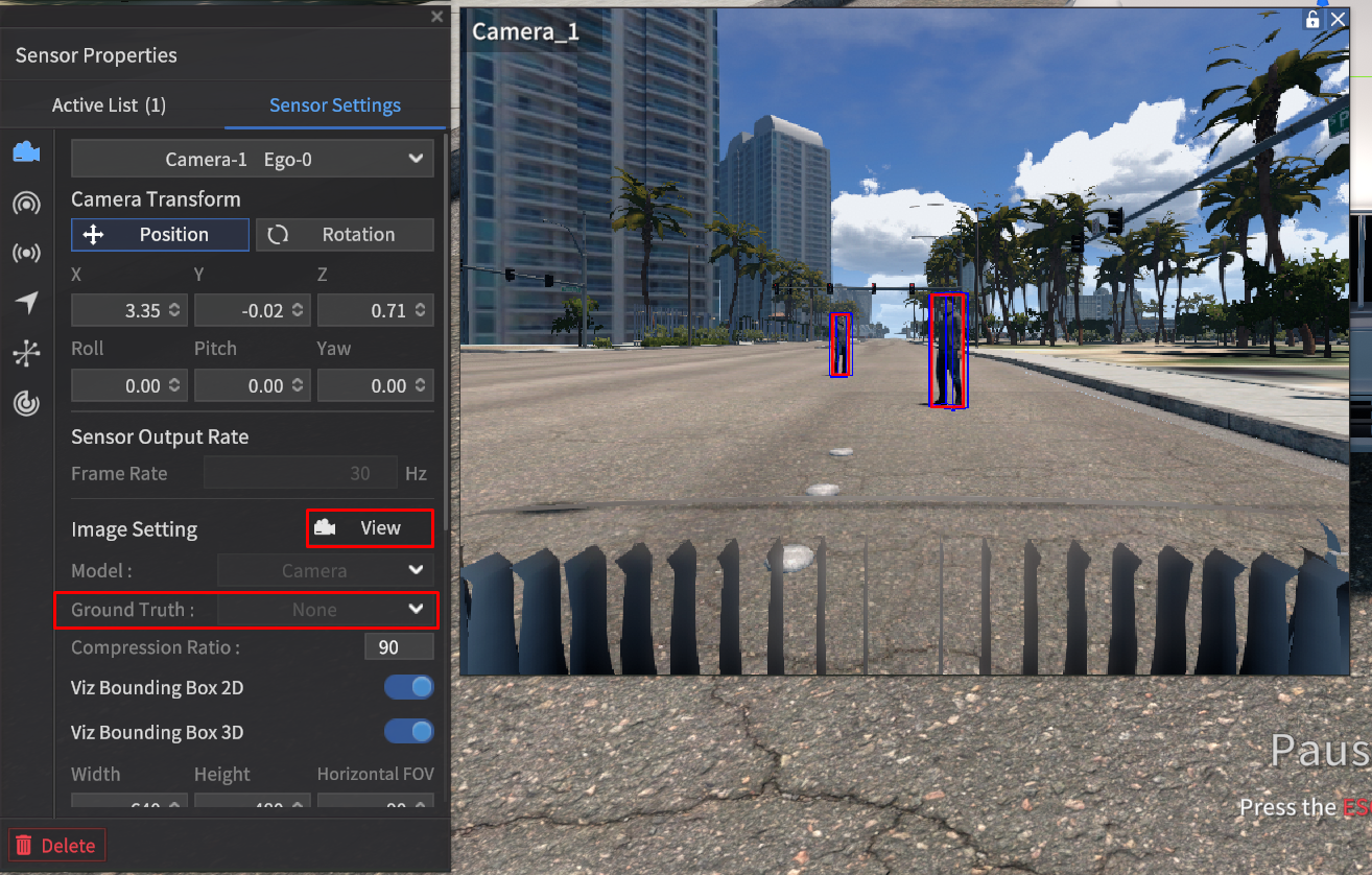
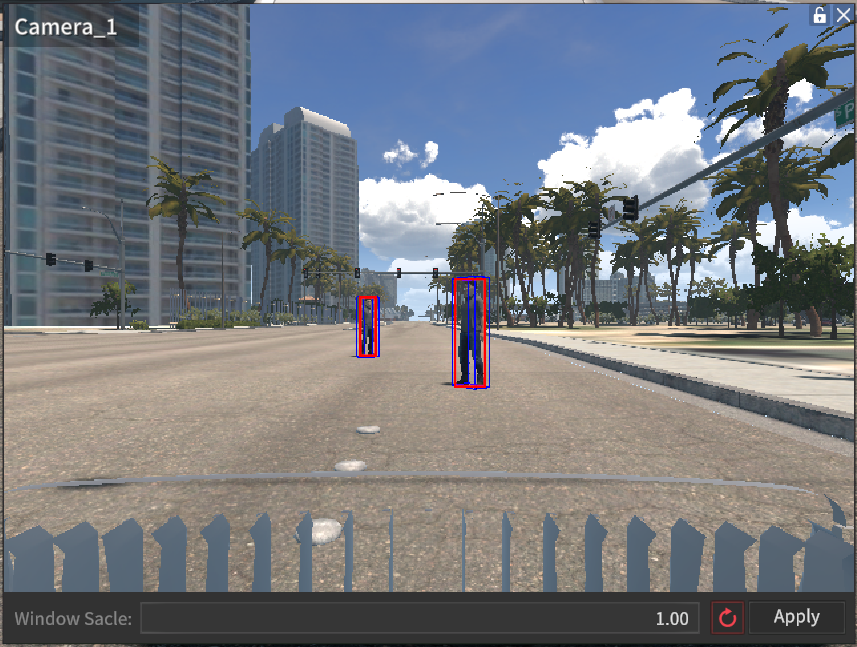
As shown in the image above, the 2D/3D Bounding Box for the traffic light object is not displayed.
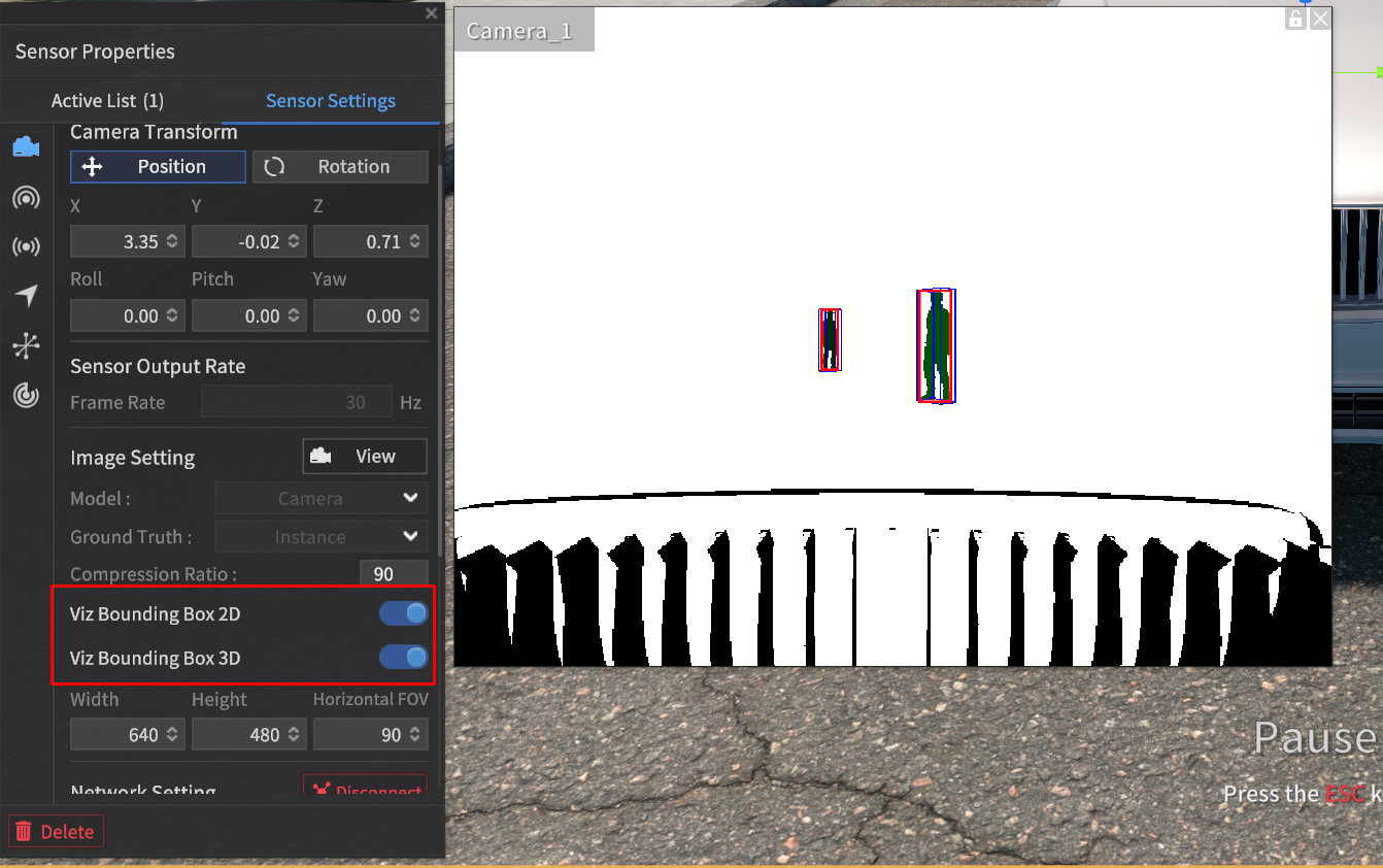
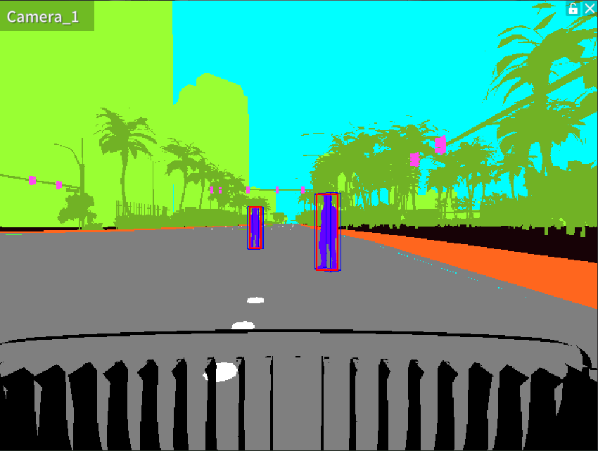
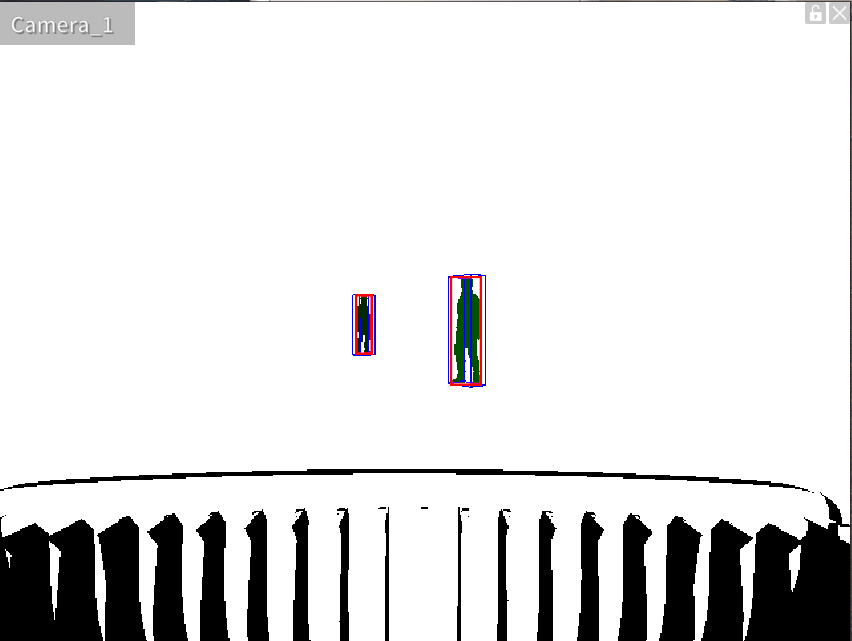
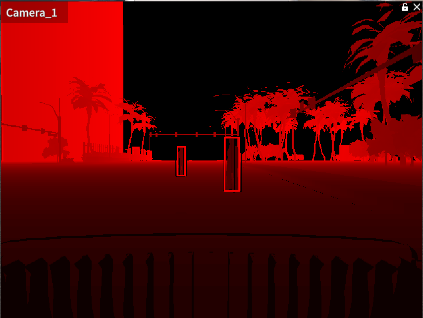
When both Viz Bounding Box 2D and 3D are enabled, they will be displayed in the same manner for other GT types such as Semantic, Instance, and Depth.
Semantic | Instance | Depth |
|---|---|---|
|
 |
 |
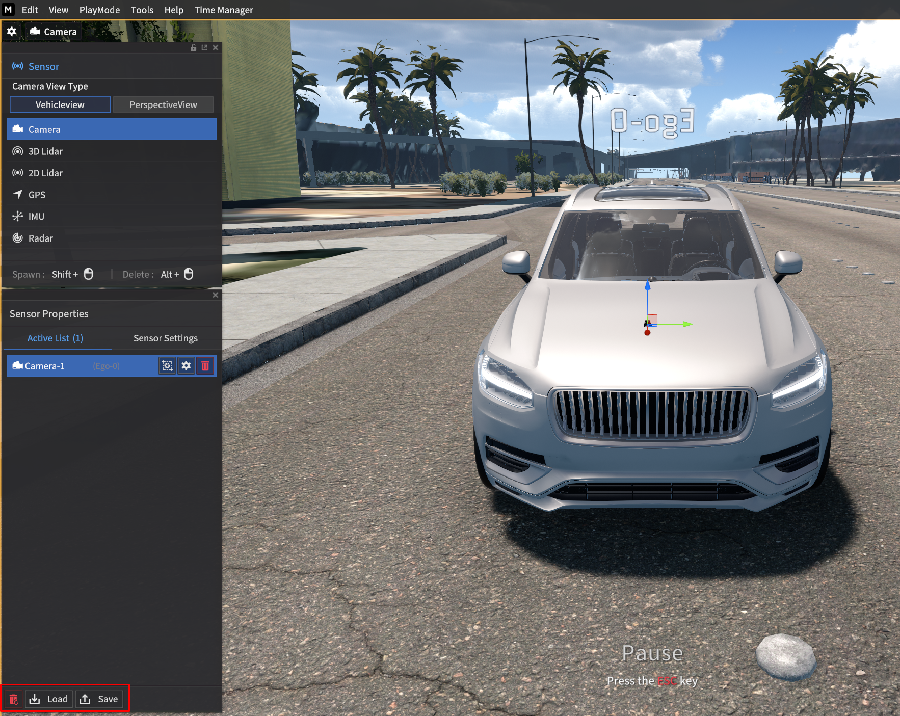
Save and Load the Sensor Settings
You can save and load the sensor settings via Sensor Edit Mode > Active List.
With Save and Load button, you can save the current sensor settings to a file (.json) or load the existing sensor configuration information.
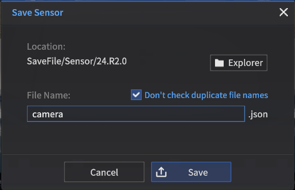
Save Sensor Settings information
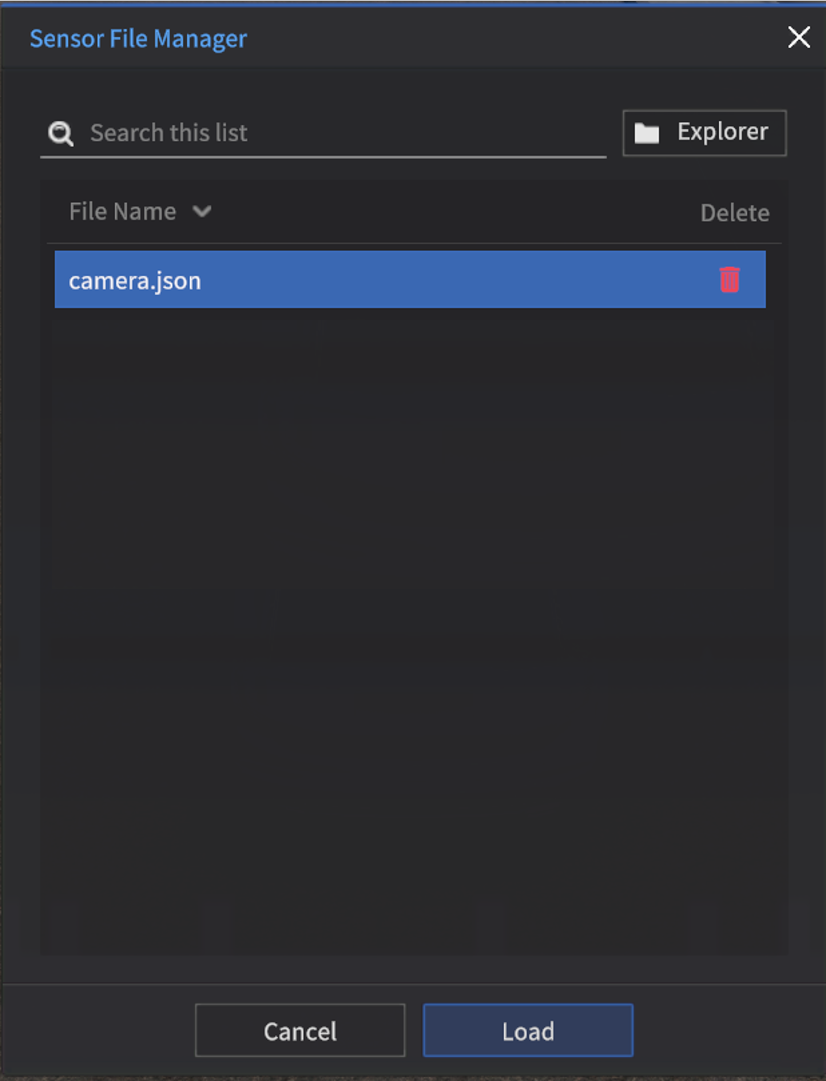
Load the saved Sensor Settings information
Clicking the Load button in the Sensor Properties open the Sensor File Manager.
The Sensor File Manager displays the currently saved sensor configuration files, allowing you to load or delete the selected file.